
Unmanned aerial vehicle object grabbing device

A technology of machine grasping and steering gear, which is applied to launching devices, unmanned aerial vehicles, motor vehicles, etc., can solve the problems of uncertain landing position accuracy of drones and only one remote control channel, and achieve light weight and structure Simple and exquisite, quick effect

Inactive Publication Date: 2016-12-21
NANJING UNIV OF SCI & TECH
View PDF7 Cites 4 Cited by
  • Summary
  • Abstract
  • Description
  • Claims
  • Application Information

AI Technical Summary

Problems solved by technology

[0004] The purpose of the present invention is to provide a drone grasping device, which solves the problems in the prior art that there is only one remote control channel and the accuracy of the landing position of the drone is uncertain

Method used


Image

  • Unmanned aerial vehicle object grabbing device
  • Unmanned aerial vehicle object grabbing device
  • Unmanned aerial vehicle object grabbing device

Examples


Embodiment Construction

[0015] The present invention will be described in further detail below with reference to the accompanying drawings.

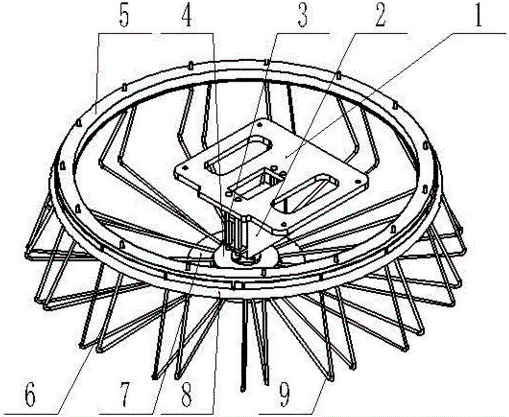
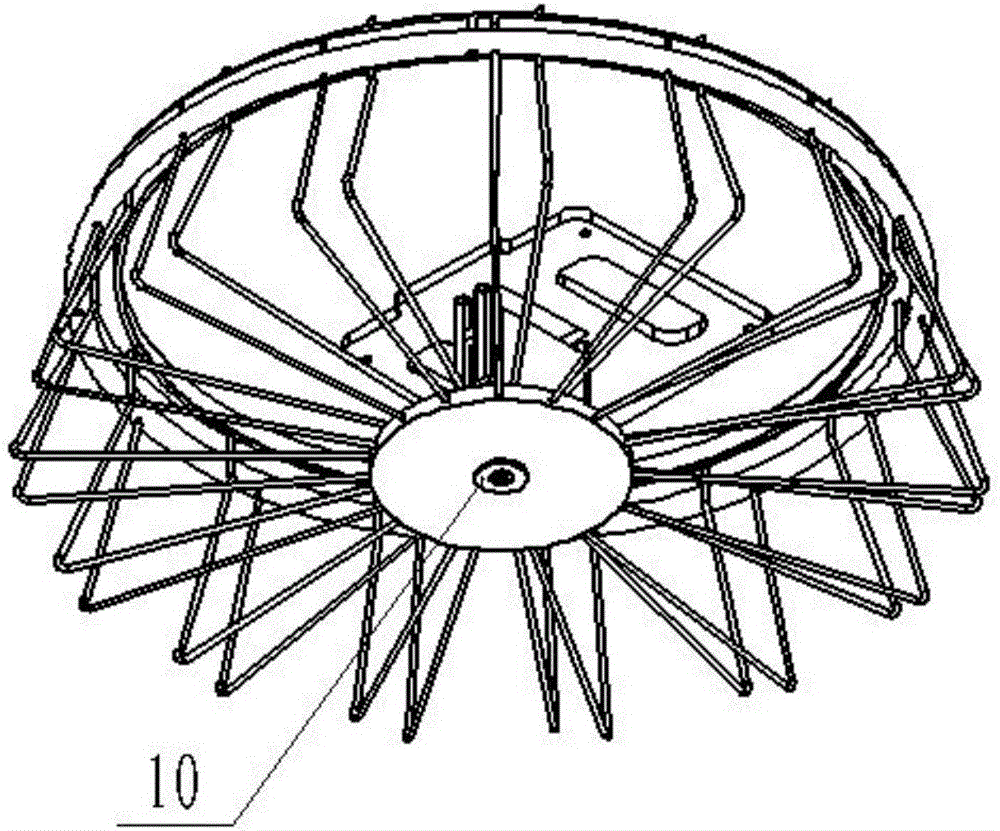
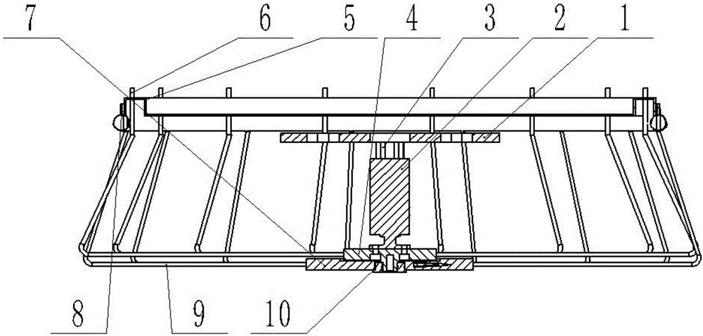
[0016] combine Figure 1~Figure 3 , an unmanned aerial vehicle grabbing device, including a steering gear frame 1, a steering gear 2, a support column 3, a rotating disk 4, an inner rotating ring 5, a rotating ring wire 6, a stationary disk 7, an outer stationary ring 8, a stationary ring The iron wire 9 and the flange bearing 10 and the rotating disk 4 are arranged on the top surface of the stationary disk 7 , and the two are connected by the flange bearing 10 , so that the rotating disk 4 can rotate around the flange bearing 10 . The outer stationary ring 8 is arranged above the rotating disk 4, the top of the outer stationary ring 8 is provided with a baffle plate, the inner rotating ring 5 is arranged in the outer stationary ring 8, and one end of several rotating ring iron wires 6 is uniformly distributed in a ring shape, and one end is connected to the in...


PUM


Abstract

The invention discloses an unmanned aerial vehicle object grabbing device. A rotary disc is arranged on the top of a static disc, and the rotary disc is connected with the static disc through a flange bearing, so that the rotary disc rotates around the flange bearing. An outer static ring is arranged above the rotary disc, a circle of baffle is arranged on the top of the outer static ring, an inner static ring is arranged in the outer static ring, one ends of multiple rotary ring iron wires are evenly distributed annularly, one ends of the rotary ring iron wires are fixedly connected with the inner rotary ring, and another ends of the rotary ring iron wires are fixedly connected with the rotary disc. One ends of multiple static ring iron wires are evenly distributed annularly, one ends of the static ring iron wires are fixedly connected with the outer static ring, and another ends of the static ring iron wires are fixedly connected with the static disc. The static ring iron wires and the rotary ring iron wires are both in an L shape, and the bottom faces of the static ring iron wires and the rotary ring iron wires are horizontal faces. An output shaft of a steering engine is connected with the flange bearing in the center of the top face of the rotary disc, the other end of the steering engine is connected with a steering engine rack through a supporting column, and the top face of the steering engine rack is used for being connected with an unmanned aerial vehicle. The problems that only one remote control channel exists in the prior art, and the landing position precision of the unmanned aerial vehicle is uncertain are solved.

Description

technical field [0001] The invention belongs to an unmanned aerial vehicle accessory, in particular to an unmanned aerial vehicle grabbing device. Background technique [0002] With the needs of applications and the development of aviation technology, there has been a worldwide upsurge in research on UAVs in recent years. The reason is that replacing manned aircraft with UAVs can reduce production costs. It is easy to transport, repair and maintain, and it does not need to consider the limit of human physical and psychological tolerance. In the future, UAVs will have broad application prospects in both military and civilian fields. In the military field, the use of UAVs for combat and reconnaissance can reduce casualties and have ultra-high overload maneuverability, which is conducive to attacking and getting rid of threats. In the civilian field, UAVs can complete heavy and repetitive or certain dangerous tasks such as resource survey, disaster reconnaissance, communicati...

Claims


Application Information

Patent Timeline
IPC IPC(8): B64C39/02B64D1/12
CPCB64C39/02B64D1/12B64U2101/60B64U10/10
Inventor 张志安盛娟红盛明杰徐文章陈庆武肖胜杰胡致远董培方王腾高逸夫
Owner NANJING UNIV OF SCI & TECH
Learn More