Punching equipment for antenna reflective surface punching

A reflective surface and punching technology, which is applied in the field of antenna processing, can solve the problems of difficult installation of radome, complex processing technology, inaccurate installation hole angle, position and aperture size, etc., and achieve low manufacturing cost, simple process and simple structure subtle effect

Active Publication Date: 2018-07-10
TONGYU COMM INC
View PDF5 Cites 0 Cited by
  • Summary
  • Abstract
  • Description
  • Claims
  • Application Information

AI Technical Summary

Problems solved by technology

[0003] In the prior art, a single hole is usually drilled or punched on the antenna reflecting surface through corresponding equipment. When there are many installation holes to be set, repeated operations are required many times. Not only the processing technology is complicated, but also the angle and position of the installation holes are likely to And the problem of inaccurate aperture size makes it difficult to install the radome on the antenna reflector

Method used


Image

  • Punching equipment for antenna reflective surface punching
  • Punching equipment for antenna reflective surface punching
  • Punching equipment for antenna reflective surface punching

Examples


Embodiment Construction

[0025] The present invention will be described in detail below in conjunction with the accompanying drawings and embodiments.

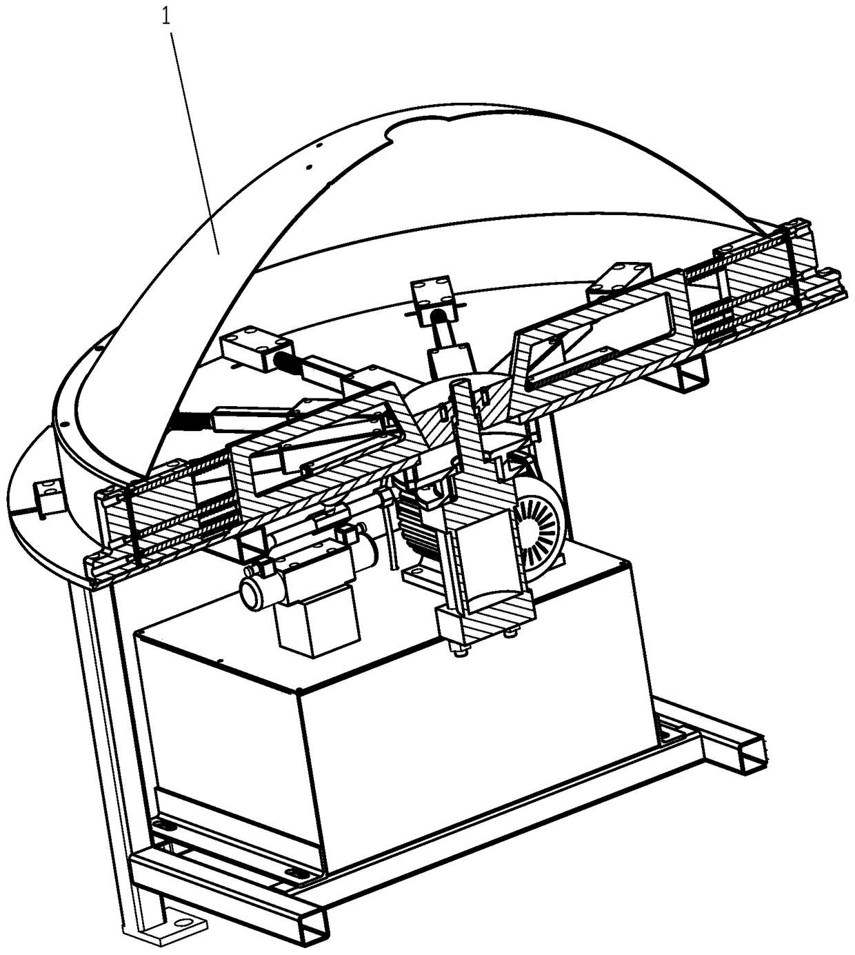
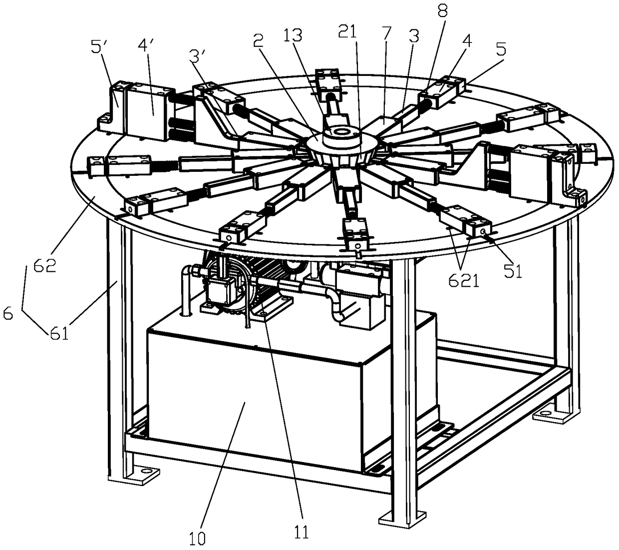
[0026] see Figure 1 to Figure 6 , the punching equipment of the embodiment of the present invention is especially suitable for punching the antenna reflective surface 1 with straight sides. The punching equipment includes: an output shaft that can be driven by a power source; A plurality of punching pins 3 that are cooperating with each other and can expand and contract along their own length direction under the drive of the output shaft; multiple sets of punches 4 and dies 5 with the same number as punches 3, each set of punches 4 and dies 5 , the punch 4 and the die 5 are relatively spaced apart, and are used to clamp and fix the antenna reflection surface 1, wherein the punch 4 and the die 5 are provided with aligned through holes 41, 51 for the punch pins 3 to pass through from the inside to the outside in sequence Then the antenna reflection su...


PUM


Abstract

The invention discloses punching equipment for punching to an antenna reflector. The punching equipment comprises an output shaft driven by a power source, a plurality of punching pins, and sets of male dies and female dies, wherein the punching pins are all arranged around the output shaft, are matched with the output shaft and can stretch under the driving of the output shaft in the self length direction; the quantity of the punching pins is the same with that of the sets of male dies and female dies, in each set of a male die and a female die, the male die and the female die are oppositely arranged at an interval, and are used for clamping and fixing the antenna reflector, the male dies and the female dies are provided with aligned penetrating holes so as to allow the punching pins to penetrate in from the inside out in sequence and further carry out punching to the antenna reflector. Due to the adoption of the implementation way, a plurality of holes can be punched in the antenna reflector in one step as to be used as mounting holes or leakage holes, the process is simple, the hole forming angle, position and aperture are accurate, and the equipment structure is simple and ingenious.

Description

technical field [0001] The invention relates to the technical field of antenna processing, in particular to a punching device for punching antenna reflective surfaces. Background technique [0002] When the antenna reflective surface is in use, in order to improve the electrical performance of the antenna reflective surface, it is often necessary to install a radome on the straight edge of the top of the antenna reflective surface. In order to install the radome, it is usually necessary to set mounting holes on the top straight side of the antenna reflective surface so that the radome can be fixed to the antenna reflective surface by screws or the like. [0003] In the prior art, a single hole is usually drilled or punched on the antenna reflecting surface through corresponding equipment. When there are many installation holes to be set, repeated operations are required many times. And the problem of inaccurate aperture size makes it difficult to install the radome on the a...

Claims


Application Information

Patent Timeline
Patent Type & Authority Patents(China)
IPC IPC(8): B21D28/26B21D28/34
Inventor 刘华宝窦华土张君赵李刚
Owner TONGYU COMM INC
Why Eureka
Try Eureka