
An Angle Limiting Mechanism of a Furniture Turning Device

A technology of flipping device and limiting mechanism, which is applied to building structures, switches with brakes, door/window accessories, etc. Inconvenient use and other problems, to achieve the effect of improving user experience, humanized design, and stable overall structure

Active Publication Date: 2017-11-10
伍志勇
View PDF1 Cites 0 Cited by
  • Summary
  • Abstract
  • Description
  • Claims
  • Application Information

AI Technical Summary

Problems solved by technology

It is said that the structure is simple, the performance is reliable, and the use is flexible. However, due to the effect of the buffer, this structure requires a large force to open or close the door, which may easily cause damage to the handle on the door or the door cannot be closed properly. And the hinge of this structure is not convenient enough to use, and cannot adjust and limit the opening angle of the furniture door, and cannot meet the needs of users.

Method used


Image

  • An Angle Limiting Mechanism of a Furniture Turning Device
  • An Angle Limiting Mechanism of a Furniture Turning Device
  • An Angle Limiting Mechanism of a Furniture Turning Device

Examples


no. 1 example

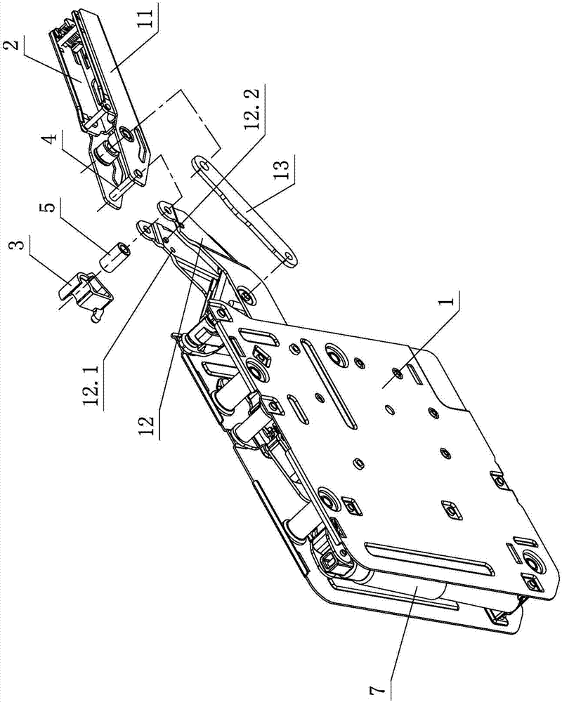
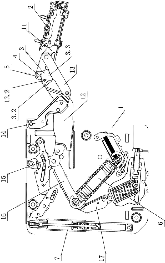
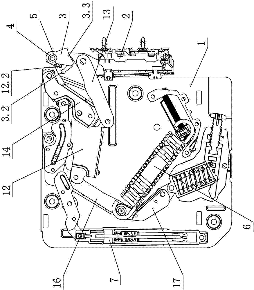
[0029] See Figure 1-Figure 4 , The angle limiting mechanism of the furniture turning device includes a turning device. The turning device includes a fixed bracket 1, a connecting arm assembly, and a fixed base 2. The connecting arm assembly is connected to the fixed bracket 1, and the fixed base 2 respectively. The fixed base 2 is connected The arm assembly is turned over and opened and closed on the fixed bracket 1. The connecting arm assembly at least includes a first connecting arm 11, a second connecting arm 12, and a third connecting arm 13. One end of the first connecting arm 11 is hinged with one end of the second connecting arm 12. The other end of the second connecting arm 12 is hinged to the fixed bracket 1, the other end of the first connecting arm 11 is connected to the fixed base 2, and the third connecting arm 13 is hinged to the first connecting arm 11 and the second connecting arm 12 respectively; the first connecting arm 11 An angle positioning member 3 is elas...

no. 2 example

[0041] See Figure 5-Figure 8 , The angle limiting mechanism of the furniture turning device is different from the first embodiment in that the angle positioning member 3 is in-line, and the upper end is provided with a clamping part 3.1, the middle part is provided with a positioning part 3.2, and the lower end is provided with a support Part 3.3, one side of the supporting part 3.3 is provided with a receiving part 3.4, the second connecting arm 12 corresponds to the receiving part 3.4, the positioning part 3.2 is respectively provided with a receiving and matching part 12.2 and a positioning matching part 12.1 on the side walls; wherein, the clamping part 3.1 It is an arc-shaped opening, the positioning part 3.2 is a positioning convex edge, the receiving part 3.4 is a receiving protrusion, the receiving and matching part 12.2 is a receiving edge, and the positioning and matching part 12.1 is a positioning edge.

[0042] Other undescribed parts are the same as the first embodim...

no. 3 example

[0044] See Figure 9-11 The angle limiting mechanism of the furniture turning device is different from the first embodiment in that one end of the elastic member 6 elastically acts on the seventh connecting arm 17 and the other end of the elastic member 6 acts elastically on the fixed bracket 1. One end of the damper 7 acts on the fourth connecting arm 14 and the other end acts on the fixing bracket 1.

[0045] Other undescribed parts are the same as the first embodiment.


PUM


Abstract

An angle limiting mechanism of a furniture overturning device comprises an overturning device body. The overturning device body comprises a fixing support, a connecting arm assembly and a fixing base. The connecting arm assembly is connected with the fixing support and the fixing base in a matched mode. The fixing base is arranged on the fixing support in overturning opening and close modes through the connecting arm assembly. The connecting arm assembly at least comprises a first connecting arm, a second connecting arm and a third connecting arm. One end of the first connecting arm is hinged to one end of the second connecting arm. The other end of the second connecting arm is hinged to the fixing support. The other end of the first connecting arm is connected with the fixing base. The third connecting arm is hinged to the first connecting arm and the second connecting arm. An angle positioning part is elastically connected to the hinged joint of the first connecting arm and the second connecting arm in a clamping mode. The angle positioning part and the second connecting arm are mutually linked, and the angle positioning part and the third connecting arm mutually act when the fixing base is opened in an overturned mode by a certain angle relative to the fixing support, so that the overturning opening angle of the overturning device body is limited. Through improvement of the structure, the angle limiting mechanism has high practicability.

Description

Technical field [0001] The invention relates to an angle limiting mechanism of a furniture turning device. Background technique [0002] The Chinese patent document number CN201339380 discloses a hinge on January 9, 2009, which includes a door box, a connecting rod, a hinge arm, a shift arm, a base, a buffer, a torsion spring, a link, and a lever drive plate. The device has a fan-shaped structure. It has a center hole and 3 circumferential holes. The center hole is movably connected to the hinged arm for positioning. 1 circumferential hole is movably connected to the piston rod end of the buffer. The remaining 2 circumferential holes are provided with shafts. The lever drive piece is provided with an end hole and a middle hole. The other end opposite to the end hole is provided with 2 fork teeth. The lever drive piece is movably connected to the hinge arm through the middle hole, so that the two fork teeth are connected to the linker. The shafts on the two circumferential holes ...

Claims


Application Information

Patent Timeline
Patent Type & Authority Patents(China)
IPC IPC(8): E05D5/02E05D11/10E05F3/20E05F5/06
CPCE05D5/0276E05D11/1028E05F3/20E05F5/06E05Y2900/20
Inventor 伍志勇
Owner 伍志勇
Learn More