Method and controller of pneumatic adjustment system for failure leakage of speed changer

A technology for adjusting systems and transmissions, applied in transmission control, testing of machines/structural components, instruments, etc., can solve problems such as switching cylinders that can no longer be operated normally, vehicle parking, etc., and achieve simple and reliable measurement results

Active Publication Date: 2016-12-21
ZF FRIEDRICHSHAFEN AG
View PDF6 Cites 1 Cited by
  • Summary
  • Abstract
  • Description
  • Claims
  • Application Information

AI Technical Summary

Problems solved by technology

Faulty leaks in the control system or in the transmission can lead to the fact that the shifting cylinders can no longer be operated properly, whereby under certain circumstances shifting can no longer be carried out reliably in the transmission
This can in some cases lead to a complete stop of the vehicle including the transmission

Method used


Image

  • Method and controller of pneumatic adjustment system for failure leakage of speed changer
  • Method and controller of pneumatic adjustment system for failure leakage of speed changer
  • Method and controller of pneumatic adjustment system for failure leakage of speed changer

Examples


Embodiment Construction

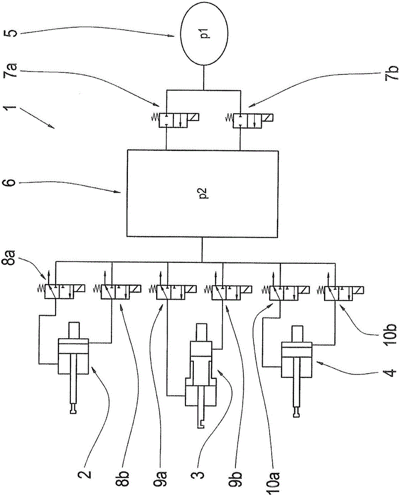
[0017] The invention relates to a method for detecting excessively high or faulty leaks in a pneumatic control system of a transmission, which would lead to the fact that normal gearshifts can no longer take place in the transmission. Such leaks are called fault leaks. Furthermore, the invention relates to a controller for carrying out the method.

[0018] figure 1 Schematically shows the basic structure of the pneumatic adjustment system for the transmission, that is, in the figure 1 The basic structure of a pneumatic control system for a combined transmission in which at least one pneumatically actuated switching cylinder 2 , 3 or 4 is formed in each transmission part of the combined transmission. figure 1 The shifting cylinder 2 shown in is the pneumatically actuated shifting cylinder of the split gear group of the combined transmission. The shifting cylinder 3 is a pneumatically actuated shifting cylinder of the main transmission of the combined transmission. The shift...


PUM


Abstract

Method for detecting an error leak in a pneumatic control system (1) of a transmission, wherein the control system (1) comprises an air reservoir (5) in which there is a first pressure, wherein the air reservoir (7) via at least a first switching valve (7a, 7b ) is coupled to an actuator space (6) of the control system (1), in which there is a second pressure, and said actuator chamber (6) via at least a respective second switching valve (8a, 8b, 9a, 9b, 10a, 10b) with the switching cylinders (2, 3, 4) is coupled. In embodiments of a circuit in the transmission an the actuator chamber (6) is on the or each first switching valve (7a, 7b) supplied air mass and air mass sum of at least one air mass in the actuator chamber (6) and an air mass in active switching cylinders (2, 3, 4 ) determined, and when the the Steller space (6) via the or each first switching valve (7a, 7b) supplied air mass is greater than the air mass amount to an error of leakage in the pneumatic control system (1) is closed.

Description

technical field [0001] The invention relates to a method for detecting faulty leaks in a pneumatic adjustment system of a transmission. The invention also relates to a controller for carrying out the method. Background technique [0002] It is known from practice to actuate shifting elements of a transmission, for example shifting cylinders of a transmission, by means of pneumatic actuating systems. Such a pneumatic adjusting system has an air reservoir which is coupled via at least one first switching valve to an adjusting chamber of the adjusting system. Starting from the control chamber of the control system, each switching cylinder can be supplied with air via at least one second switching valve. Faulty leaks in the control system or in the transmission can lead to the fact that the shifting cylinders can no longer be operated properly, whereby under certain circumstances shifting can no longer be carried out reliably in the transmission. This can in some cases lead t...

Claims


Application Information

Patent Timeline
Patent Type & Authority Applications(China)
IPC IPC(8): F16H61/12
CPCF16H61/12F16H2061/1208F16H61/0206G01M3/26G01M3/2876G01M3/3263
Inventor 阿兰·蒂尔里·查马肯坎德
Owner ZF FRIEDRICHSHAFEN AG
Why Eureka
Try Eureka