
High-impact-resistant wall surface pressure measurement device

A measuring device and wall technology, applied in the direction of measuring blasting force, etc., can solve the problems of poor stability, affecting the test results, unable to obtain the shock wave pressure curve, etc., and achieve the effect of reducing the impact and inhibiting the transmission.

Inactive Publication Date: 2016-12-21
XIAN MODERN CHEM RES INST
View PDF4 Cites 11 Cited by
  • Summary
  • Abstract
  • Description
  • Claims
  • Application Information

AI Technical Summary

Benefits of technology

This new technology helps measure how well things stand out from their surroundings by preventing any unwanted movement or shaking that could affect its performance. It uses an isolated part called a semirigid material to create a tight connection with both parts while still allowing for flexibility during use. By reducing this vibrations transmitted through it, we can accurately describe what's going on inside our walls without being affected too much.

Problems solved by technology

This patented technical problem addressed by this patents relates to improving the design and manufacture of firearms that operate at extreme temperatures during their operation for better safety purposes. Current testing techniques used involve exposing the sensors inside the gun body to severe environments such as high temperature (above 2000°C) while they work properly. However, these tests cannot provide detailed analysis about how well the measurements were taken over time.

Method used


Image

  • High-impact-resistant wall surface pressure measurement device
  • High-impact-resistant wall surface pressure measurement device
  • High-impact-resistant wall surface pressure measurement device

Examples


Embodiment Construction

[0022] The present invention will be further described in detail below in conjunction with the accompanying drawings and preferred embodiments.

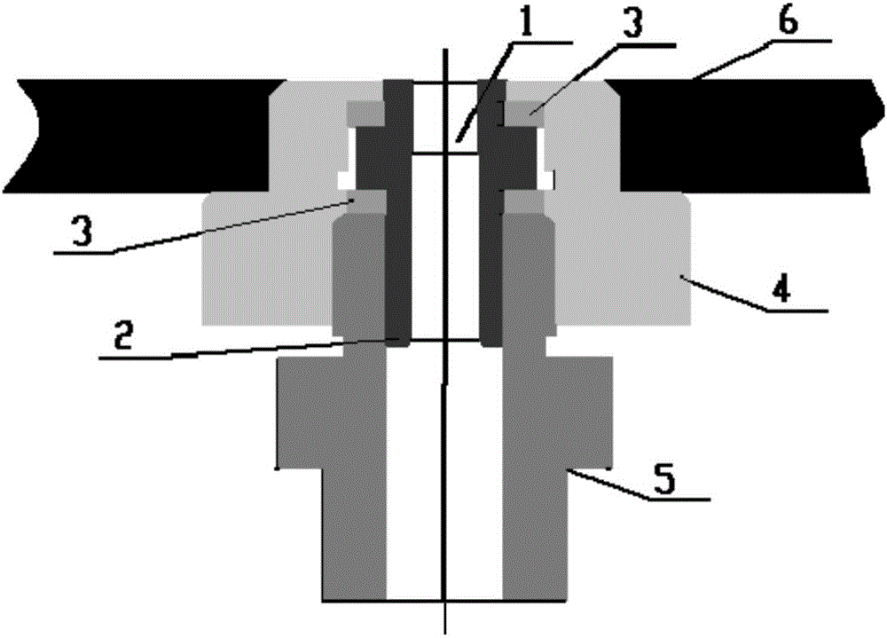
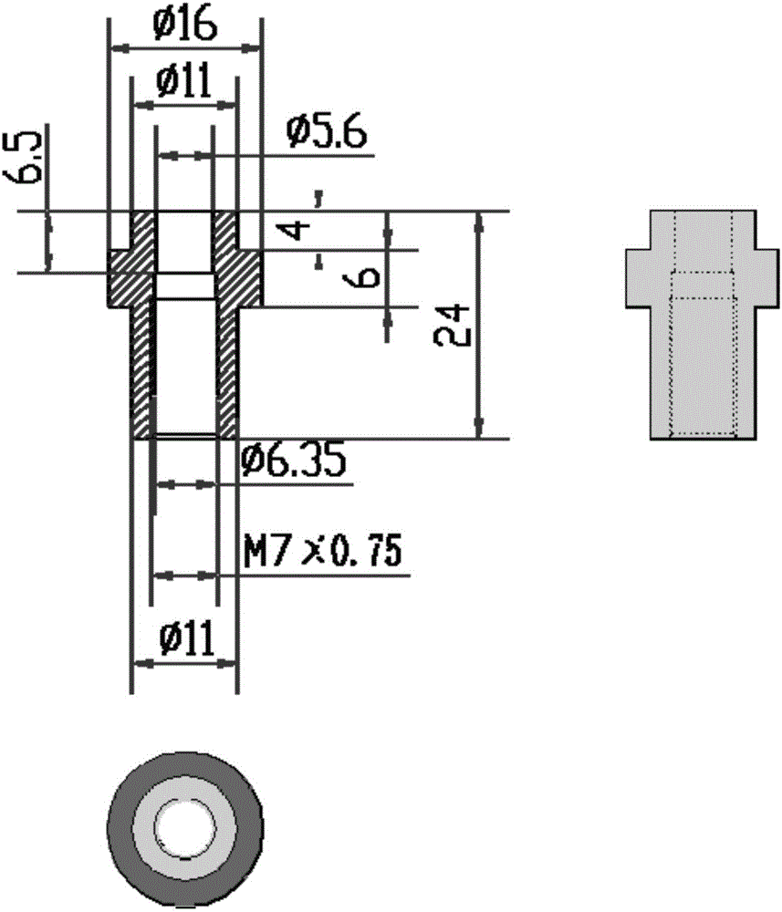
[0023] Such as figure 1 As shown, the preferred embodiment of the present invention is a high-impact wall pressure measurement device, which is composed of a sensor 1 , a mount 2 , an isolation ring 3 , a base 4 , and a compression screw 5 . The sensor 1 is installed in the center hole of the mounting base 2 through threaded connection, there is a copper washer on the shoulder of the sensor, and an isolation ring 3 is respectively installed on the two end faces of the boss of the mounting base 2, and then the mounting base 2 is placed on the base 4 Inside, fasten it by the compression screw 5. The end surface of the mounting seat 2 is flush with the wall surface 6 to avoid disturbance to the shock wave flow field and ensure that the measurement position is consistent with the wall surface.

[0024] The vibration isolation of the me...


PUM


Abstract

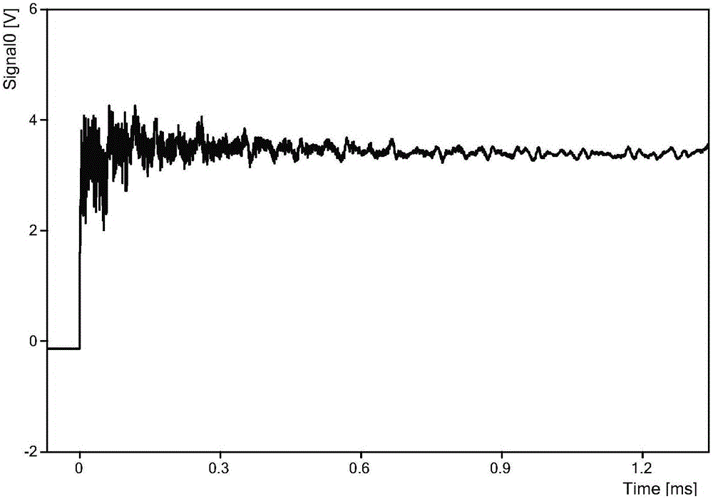
The invention discloses a high-impact wall pressure measuring device, which is mainly characterized in that the pressure measuring device is composed of a mounting seat, an isolation ring, a base, a compression screw, and a sensor; the sensor is installed in the central through hole of the mounting seat, The mounting seat is connected with the base and the compression screw through the isolation ring, and the compression screw is pressed into the base, and the base and the wall are fastened; when the shock wave or wall vibration causes the base to vibrate, the vibration of the mounting base is caused. However, due to the two polyethylene isolation rings, there is a non-rigid contact between the base and the mounting seat, which effectively isolates the transmission of vibration to the mounting seat. The remarkable advantage of the present invention is that it can isolate the propagation of the base vibration to the mounting base, effectively eliminate the influence of the base vibration of the explosion field on the performance of the sensor, realize the purpose of obtaining a complete and accurate shock wave pressure change curve, and meet the wall shock wave pressure of the internal explosion field Test requirements.

Description


Claims


Application Information

Patent Timeline
Owner XIAN MODERN CHEM RES INST
Learn More