Analysis model construction and verification method for revealing wear difference of cutter teeth of high-feed milling cutter

A technology for analyzing models and verifying methods, applied in the direction of geometric CAD, etc., can solve problems such as the inability to fully describe the wear state of the flank, the inability to accurately describe the difference in the wear state of different cutter teeth, and the single maximum wear amount.

Active Publication Date: 2020-01-17
HARBIN UNIV OF SCI & TECH
View PDF7 Cites 5 Cited by
  • Summary
  • Abstract
  • Description
  • Claims
  • Application Information

AI Technical Summary

Problems solved by technology

[0004] The purpose of the present invention is to provide an analytical model construction and verification method for revealing the difference in tooth wear of high-feed milling cutters, so as to solve the problem that the existing identification methods of tooth wear characteristics are mostly based on a single maximum wear amount, which cannot Comprehensively describe the wear state of a single cutter tooth flank, but also cannot accurately describe the difference in wear state between different cutter teeth. The identification of the characteristics affected by the wear difference to achieve the purpose of verifying the analysis model of the wear difference

Method used


Image

  • Analysis model construction and verification method for revealing wear difference of cutter teeth of high-feed milling cutter
  • Analysis model construction and verification method for revealing wear difference of cutter teeth of high-feed milling cutter
  • Analysis model construction and verification method for revealing wear difference of cutter teeth of high-feed milling cutter

Examples


Embodiment approach 1

[0048] Implementation Mode 1: The details are as follows:

[0049] 1. Identification method of influencing factors of tooth wear difference of high-feed milling cutter

[0050] In order to identify the factors affecting the difference in tooth wear of high-feed milling cutters, milling experiments with high-feed milling cutters were carried out. Before the start of each experiment, the tooth error of the milling cutter was measured. After the experiment, the collected milling vibration signals were filtered, and the maximum value, minimum value, effective value, main frequency and spectrum value of the milling vibration acceleration under different cutting strokes were extracted.

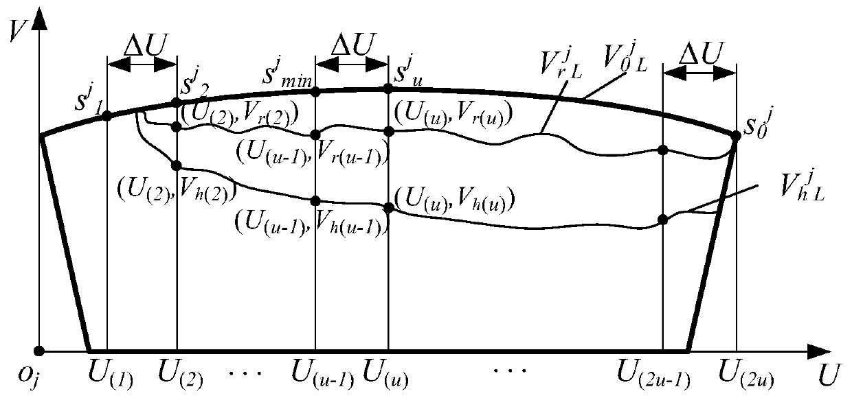
[0051] After the experiment, the flank wear morphology of each tooth of the high-feed milling cutter was detected, and the wear state diagram of the flank flank of the bottom edge of the tooth under different cutting stroke conditions was obtained. in point s j min with dot s j u The horizonta...

Embodiment 1

[0118] Implementation example 1: Identification method of influencing factors of tooth wear difference of high-feed milling cutter

[0119]In order to identify the factors affecting the difference in tooth wear of high-feed milling cutters, 10 sets of milling experiments were carried out using high-feed milling cutters (F2330) produced by Walter Company. The spindle speed n used in the experiments was 1143r / min, and the feed rate v f 500mm / min, milling depth a p 0.5mm, milling width a e is 16mm, and the milling stroke L is 0.5m, 1m,...,5m. Before the start of each group of experiments, the axial error of the milling cutter tooth (Δc j min ) and radial error (Δr 0 j ) for measurement and the measurement results are shown in Table 2.

[0120] The experiment of milling titanium alloy was carried out on the three-axis milling machining center (VDL-1000E) produced by Dalian Machine Tool Works. During the milling experiment of titanium alloy, the vibration signal generated b...

Embodiment 2

[0136] Implementation example 2: Construction method of high-feed milling cutter tooth wear difference analysis model

[0137] Describing the dynamic cutting behavior of milling cutters and cutter teeth during milling titanium alloys is the key to clarify the cause of differential wear of milling cutter cutter teeth. In order to obtain the changing characteristics of the milling cutter’s cutting pose, quantitatively describe the dynamic cutting behavior of the milling cutter, and establish a cutting motion analysis model of the milling cutter, such as Figure 4 The meaning of each parameter in the figure is shown in Table 2.

[0138] Table 2 Explanation of variables in the analysis model of milling cutter tooth cutting motion

[0139]

[0140] Depend on Figure 4 It can be seen that the coordinate system o d v -a i v b i v c i v , o d -a i b i c i , o g -x g the y g z g The relationship between coordinate changes is shown in formula (6). Among them, the t...


PUM


Abstract

The invention discloses an analysis model construction and verification method for revealing wear difference of cutter teeth of a high-feed milling cutter. The invention belongs to the technical fieldof milling cutter teeth. In the prior art, in the milling process of the high-feed milling cutter, the contact length and the contact depth of the cutter teeth are increased nonlinearly, and heat isdissipated rapidly due to idle cutting, and the instantaneous cutting positions and postures of the cutter teeth are changed due to impact and vibration generated by intermittent cutting of a millingcutter, and the abrasion degrees of the cutter teeth of the milling cutter are remarkably different, and difference influence factors of the cutter teeth are difficult to recognize effectively. The analysis model construction and verification method can accurately and effectively identify the influence factors of the wear difference of the cutter teeth of the high-feed milling cutter, constructs acutter tooth wear difference analysis model, accurately describes milling cutter errors, pose changes and workpiece geometric structure characteristic changes in the high-feed milling cutter millingprocess, provides a cutter tooth abrasion area boundary recognition method, accurately recognizes cutter tooth rear cutter face abrasion upper and lower boundary distribution and change characteristics, and finally verifies the effectiveness of the analysis model.

Description

technical field [0001] The invention relates to an analysis model construction and verification method for the wear difference of milling cutter teeth, in particular to a method for identifying factors affecting the wear difference of high-feed milling cutter teeth; construction of an analysis model for wear difference of high-feed milling cutter teeth method; high-feed milling cutter tooth wear area boundary recognition method; high-feed milling cutter tooth differential wear analysis model verification method; belongs to the field of milling cutter tooth technology analysis. Background technique [0002] During the milling process of high-feed milling cutters, the characteristics of tool vibration and impact change all the time. The existing wear difference analysis models cannot fully reflect the influence of process parameters, milling cutter errors and milling cutter poses on wear differences, and at the same time cannot It reflects the changing characteristics of the g...

Claims


Application Information

Patent Timeline
Patent Type & Authority Applications(China)
IPC IPC(8): G06F30/17
Inventor 赵培轶姜彬左林晗
Owner HARBIN UNIV OF SCI & TECH
Why Eureka
Try Eureka