
A kind of motor and its rotor core

A rotor core and motor technology, which is applied in the field of motors, can solve the problems of limited placement space of magnetic steel and deformation of rotor core, and achieve the effects of avoiding limited placement space, improving strength, and avoiding assembly deformation

Active Publication Date: 2019-01-25
ZHUHAI GREE REFRIGERATION TECH CENT OF ENERGY SAVING & ENVIRONMENTAL PROTECTION
View PDF5 Cites 0 Cited by
  • Summary
  • Abstract
  • Description
  • Claims
  • Application Information

AI Technical Summary

Problems solved by technology

[0007] In view of this, the purpose of the present invention is to provide a rotor core of a motor, which can solve the problem that the rotor core is easily deformed during assembly, and can avoid the problem of limited space for placing magnetic steel

Method used


Image

  • A kind of motor and its rotor core
  • A kind of motor and its rotor core
  • A kind of motor and its rotor core

Examples


Embodiment Construction

[0027] The purpose of this specific embodiment is to provide a rotor core of a motor, which can solve the problem that the rotor core is easily deformed during assembly, and can avoid the problem of limited space for placing the magnetic steel. The purpose of this specific embodiment is also to provide a motor including the above-mentioned rotor core.

[0028] Hereinafter, an embodiment will be described with reference to the drawings. In addition, the examples shown below do not limit the content of the invention described in the claims in any way. In addition, all the contents of the configurations shown in the following embodiments are not limited to be essential to the solutions of the invention described in the claims.

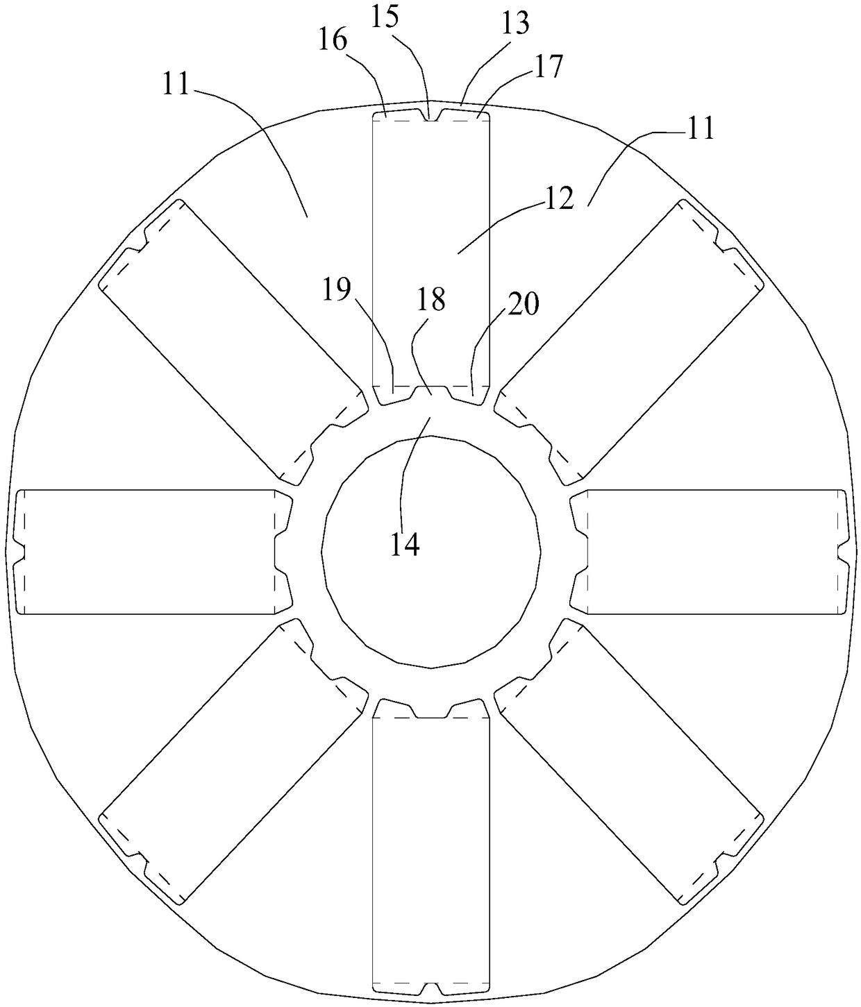
[0029] Please refer to Figure 1-Figure 5 , the rotor core of the motor provided in this embodiment includes a plurality of magnetic pole parts 11 and a plurality of magnetic steel insertion parts 12, wherein all the magnetic pole parts 11 and all the m...


PUM


Abstract

The invention discloses a motor and a rotor core thereof. The rotor core comprises a plurality of magnetic pole parts and magnetic steel inserting parts, wherein the plurality of magnetic pole parts are distributed in a circumferential direction of the rotor core; the magnetic steel inserting parts are alternatively arranged with the magnetic pole parts one by one; any two adjacent magnetic pole parts are connected through an outer connecting part close to the outer edge of the rotor core and an inner connecting part close to the center of the rotor core; first bulge parts which protrude to the magnetic steel inserting parts are arranged at the outer connecting parts; the first bulge parts can be propped against outer side surfaces of magnetic steel inserted into the magnetic steel inserting parts; and a first air gap part and a second air gap part are respectively formed in two side parts of each first bulge part. Due to the arrangement, the rotor core of the motor disclosed by the invention is capable of solving the problems that the rotor core is liable to deform when being assembled and a magnetic steel holding space is limited.

Description

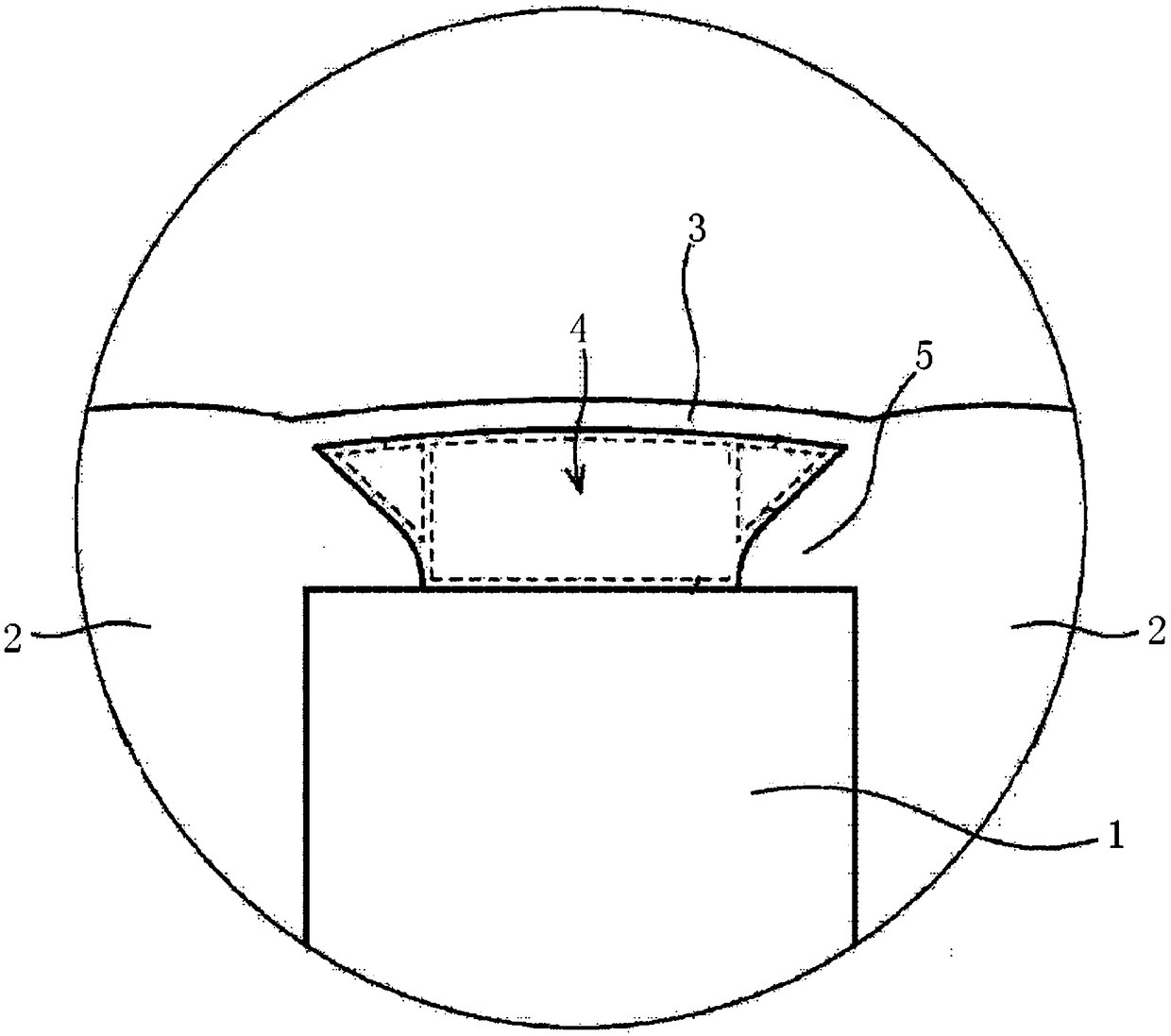
technical field [0001] The invention relates to the technical field of motors, more specifically, to a motor and its rotor core. Background technique [0002] The rotor core of the motor is composed of multiple layers of stacked steel plates, and the rotor core is provided with a plurality of magnetic pole parts and magnetic steel slots distributed along the circumferential direction. The magnetic pole parts and magnetic steel slots are arranged at intervals one by one. The magnetic steel slots are Magnet insert. [0003] Please refer to figure 1 , the outer parts of two adjacent magnetic pole parts 2, that is, the parts near the outer edge of the rotor core, are connected by the outer connecting part 3, and the inner parts of two adjacent magnetic pole parts 2, that is, the parts near the center of the rotor core The parts are connected by the inner connecting part. [0004] In order to prevent the magnetic flux of the magnetic steel insertion part 1 from leaking toward ...

Claims


Application Information

Patent Timeline
Patent Type & Authority Patents(China)
IPC IPC(8): H02K1/27
CPCH02K1/27
Inventor 刘伟健谢芳焦雷钟成堡
Owner ZHUHAI GREE REFRIGERATION TECH CENT OF ENERGY SAVING & ENVIRONMENTAL PROTECTION
Learn More