Detection device and adjusting method for objective lens roof of photo-etching machine

A detection device and a technology for engraving objects, which are applied in the field of lithography machines, can solve problems such as compact space layout, low precision indicators, and affecting installation accuracy, and achieve the effects of avoiding space constraints, long detection strokes, and high adjustment accuracy

Active Publication Date: 2013-01-23
SHANGHAI MICRO ELECTRONICS EQUIP (GRP) CO LTD
View PDF0 Cites 0 Cited by
  • Summary
  • Abstract
  • Description
  • Claims
  • Application Information

AI Technical Summary

Problems solved by technology

In the lithography machine, the measurement reference of Rz is on the mask table interferometer, and the top of the objective lens 42 is provided with an objective lens top plate 43, and the installation accuracy of the upper surface of the objective lens top plate 43 in the Rz direction directly affects the installation of the mask pre-alignment sensor Accuracy, if the installation of the objective lens top plate 43 is not in place, it will directly affect the installation accuracy of the objective lens top plate to the mask table interferometer, thereby affecting the installation accuracy of the mask table interferometer, and ultimately affecting the exposure yield of the lithography machine
[0004] The distance between the positioning pin 44 of the objective lens interface and the positioning surface of the objective lens top plate 43 is relatively far, usually about 800 mm. If traditional mechanical inspection tooling is used, the accuracy can only reach about ±700 urad, which is far below the accuracy index required by the product, and The structure of the lithography machine is complex and the spatial layout is compact. The detection device of the objective lens top plate of the lithography machine in the prior art cannot detect and adjust the position of the upper surface of the objective lens top plate 43 in the Rz direction on-line.

Method used


Image

  • Detection device and adjusting method for objective lens roof of photo-etching machine
  • Detection device and adjusting method for objective lens roof of photo-etching machine
  • Detection device and adjusting method for objective lens roof of photo-etching machine

Examples


Embodiment Construction

[0035] The following will combine Figure 2 to Figure 9 The detection device and adjustment method of the objective lens top plate of the lithography machine of the present invention will be further described in detail.

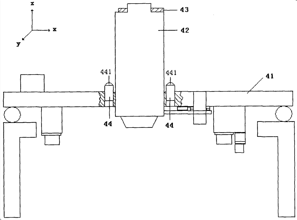
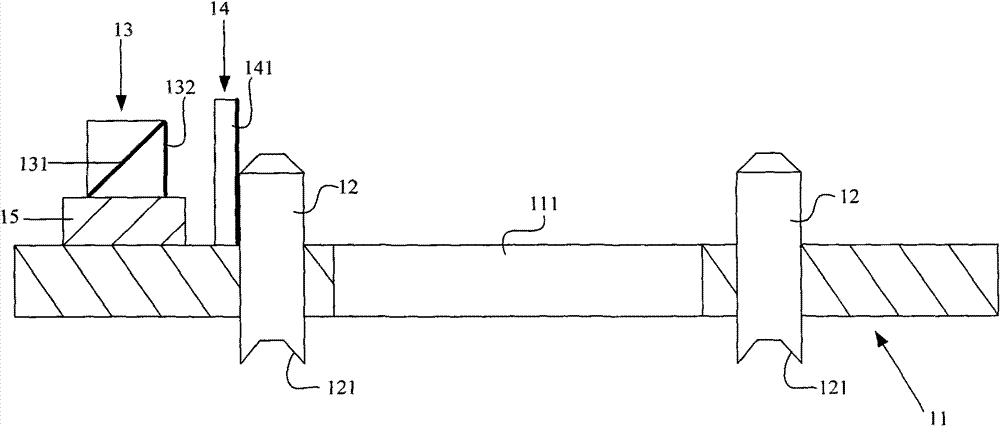
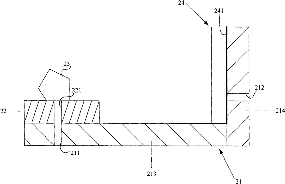
[0036] The detection device of the objective lens top plate of the lithography machine of the present invention comprises a lower plate assembly, an upper plate assembly, an autocollimation telescope and an objective lens top plate reference mirror;

[0037] The outgoing beam of the self-collimating telescope is incident on the lower plate assembly, a part of the beam incident on the lower plate assembly is directly reflected back to the self-collimating telescope by the lower plate assembly, and the rest is passed through the After being reflected by the lower plate assembly, it enters the upper plate assembly, and the light beam injected into the upper plate assembly is reflected by the upper plate assembly multiple times and then hits the objective top plate...


PUM


Abstract

The invention relates to a detection device and an adjusting method for an objective lens roof of a photo-etching machine. The device comprises a lower plate component, an upper plate component, an auto-collimating telescope and an objective lens roof reference lens, wherein an emergent beam of the auto-collimating telescope is sent to the lower plate component; one part of the light beam sent tothe lower plate component is directly reflected to the auto-collimating telescope by the lower plate component; the other part of the light beam is reflected to the upper plate component by the lowerplate component; the light beam which reaches the upper plate component is repeatedly reflected by the upper plate component and then is reflected to the objective lens roof reference lens; and then the light beam is reflected to the auto-collimating telescope along the original light path after being reflected by the objective lens roof reference lens. According to the detection device and the adjusting method for the objective lens roof of the photo-etching machine provided by the invention, by detecting the parallel degree of the emergent beam of the auto-collimating telescope and the reflected light beam of the objective lens roof reference lens, the position of the upper surface of the objective lens roof in the Rz direction can be adjusted. Besides, the adjusting precision is high.

Description

technical field [0001] The invention relates to a lithography machine, in particular to a detection device and an adjustment method for an objective lens top plate of a lithography machine. Background technique [0002] In the whole machine integration process of the lithography machine, the installation and inspection of most parts and components need to use high-precision adjustment tooling to achieve the integration accuracy of the lithography machine. [0003] see figure 1 , take the plane where the upper surface of the main substrate 41 of the lithography machine is located as the XY plane to establish a three-dimensional coordinate system, point the right thumb to the positive direction of the Z axis, and the other four fingers to make a fist, and the direction of the other four fingers to make a fist is defined as the Rz direction, similarly Define the Rx and Ry directions. In the lithography machine, the measurement reference of Rz is on the mask table interferomet...

Claims


Application Information

Patent Timeline
Patent Type & Authority Patents(China)
IPC IPC(8): G03F7/20G01M11/00
Inventor 施胜男姜福君
Owner SHANGHAI MICRO ELECTRONICS EQUIP (GRP) CO LTD
Why Eureka
Try Eureka