
Television network monitoring system

A monitoring system and TV network technology, applied in TV, electrical components, selective content distribution, etc., can solve the problems that real-time remote monitoring and management cannot be realized, and users cannot view anytime and anywhere, so as to achieve the effect of real-time remote monitoring and management

Inactive Publication Date: 2016-12-21
ANHUI RUIHONG MDT INFOTECH
View PDF4 Cites 2 Cited by
  • Summary
  • Abstract
  • Description
  • Claims
  • Application Information

AI Technical Summary

Problems solved by technology

[0005] The technical problem to be solved by the present invention is to provide a real-time remote monitoring and management, and the user can view the TV network anytime and anywhere, aiming at the defects of the prior art that it cannot realize real-time remote monitoring and management, and users cannot view the TV network anytime and anywhere. Situational TV network monitoring system

Method used


Image

  • Television network monitoring system
  • Television network monitoring system
  • Television network monitoring system

Examples


Embodiment Construction

[0021] The following will clearly and completely describe the technical solutions in the embodiments of the present invention with reference to the accompanying drawings in the embodiments of the present invention. Obviously, the described embodiments are only some, not all, embodiments of the present invention. Based on the embodiments of the present invention, all other embodiments obtained by persons of ordinary skill in the art without making creative efforts belong to the protection scope of the present invention.

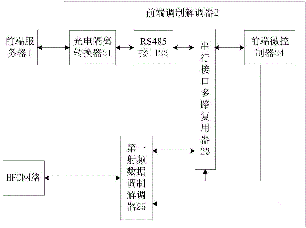
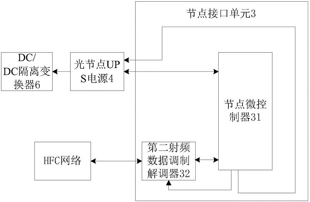
[0022] In the embodiment of the TV network monitoring system of the present invention, the structural diagram of the TV network monitoring system is as follows figure 1 shown. figure 1 Among them, the TV network monitoring system includes a front-end server 1, a front-end modem 2, a node interface unit 3, an optical node UPS power supply 4 and a mobile terminal 5, wherein the mobile terminal 5 is installed with a video network monitoring APP for querying monit...


PUM


Abstract

The invention discloses a television network monitoring system, which comprises a front-end server, a front-end modulator-demodulator, a node interface unit, an optical node UPS power supply and a mobile terminal, wherein the mobile terminal is provided with a video network monitoring APP used for querying monitoring data; the front-end server is connected with the front-end modulator-demodulator via an RS485 communication cable; the front-end modulator-demodulator controls the optical node UPS power supply by means of the node interface unit through an HFC network; the front-end server sends the monitoring data to the mobile terminal for display through a wireless network; the front-end modulator-demodulator comprises a photoelectric isolation converter, an RS485 interface, a serial interface multiplexer, a front-end microcontroller and a first radio-frequency data modulator-demodulator; and the node interface unit comprises a second radio-frequency data modulator-demodulator and a node microcontroller. The television network monitoring system can realize real-time remote monitoring and management, and allows the user to check the television network situation anywhere and anytime.

Description

technical field [0001] The invention relates to the field of network monitoring, in particular to a television network monitoring system. Background technique [0002] Cable television broadband two-way comprehensive service function network is the basic framework of the future information highway. At present, the two-way cable TV transmission system uses the optical cable as the main line of the optical cable / coaxial cable hybrid network (HFC). convert. Compared with the original one-way cable TV transmission network, because the function of the one-way cable TV transmission network is relatively simple, the equipment is relatively simple, and there is no requirement for network management. With the development of the two-way cable TV network, the scope of the network is getting bigger and bigger, the functions are more and more, the technology is more and more complex, and the importance of network management is becoming more and more obvious, especially the monitoring a...

Claims


Application Information

Patent Timeline
Patent Type & Authority Applications(China)
IPC IPC(8): H04N21/647H04N17/00
CPCH04N21/64723H04N17/00
Inventor 谢海亭
Owner ANHUI RUIHONG MDT INFOTECH
Learn More