
Coiler device provided with chute roller

A technology of winding device and chute roller, applied in manufacturing tools, metal processing equipment, metal rolling, etc., can solve the problems of large bulging of metal plates, inability to coil metal plates, and inability to guide metal plates smoothly.

Active Publication Date: 2016-12-21
PRIMETALS TECHNOLOGIES JAPAN LTD +1
View PDF9 Cites 0 Cited by
  • Summary
  • Abstract
  • Description
  • Claims
  • Application Information

AI Technical Summary

Problems solved by technology

[0008] However, after passing through the pinch rollers, the metal plate is guided to the mandrel by changing the plate passing angle obliquely downward. However, when the metal plate is a high-strength and thick material, there may be a gap between the pinch rolls and the mandrel. Make the metal plate bend greatly towards the upper surface of the coiling path
As a result, the angle at which the front end of the metal plate enters between the mandrel and the roll-helping roller changes, and the front end of the metal plate cannot be smoothly guided at the roll-helping baffle, and the bulge of the metal plate becomes too large, sometimes unable to Coil the sheet metal onto the mandrel

Method used


Image

  • Coiler device provided with chute roller
  • Coiler device provided with chute roller
  • Coiler device provided with chute roller

Examples


no. 1 approach

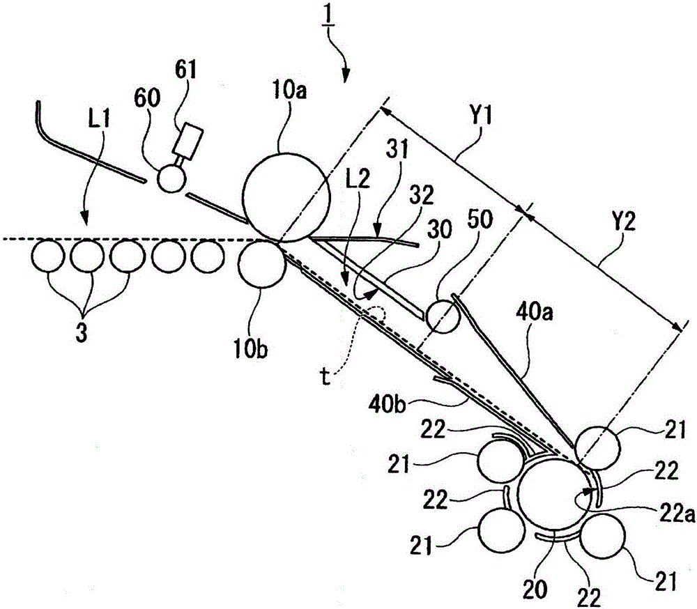
[0031] figure 1 It is a configuration diagram showing the winding device 1 according to the first embodiment of the present invention.

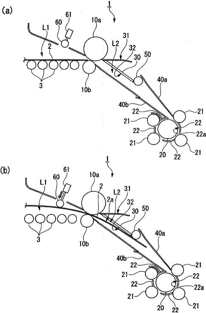
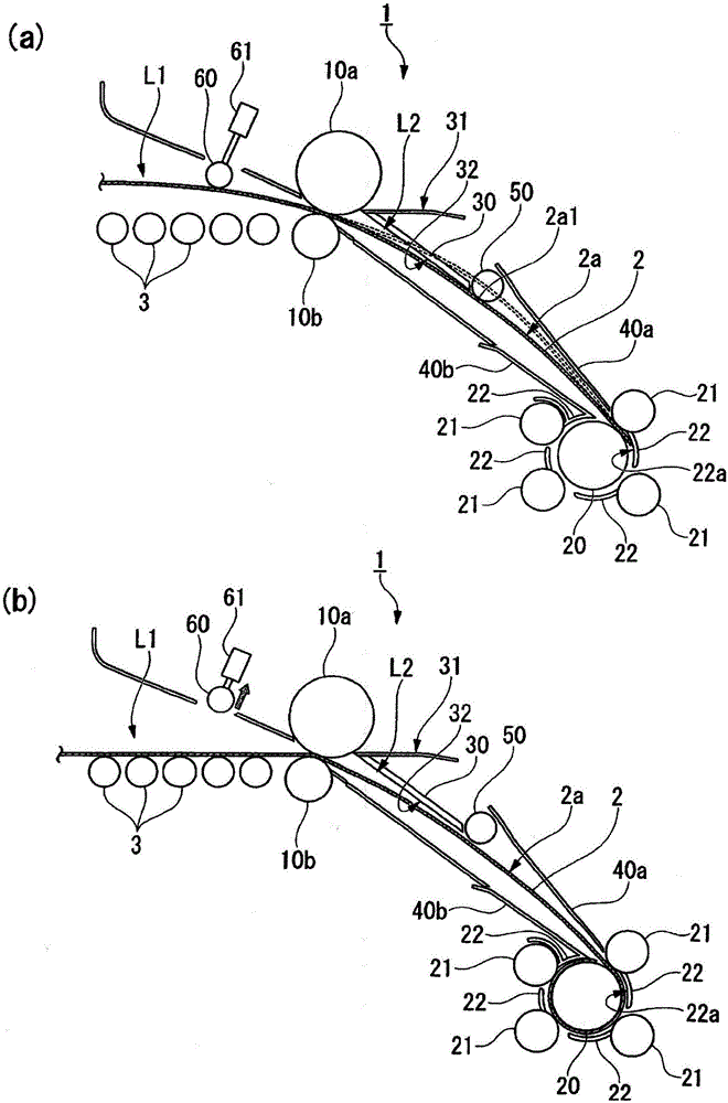
[0032] The coiling device 1 of this embodiment is arranged on the downstream side of a rolling mill not shown, and passes through the rolling mill and conveys the metal plate 2 along the transport path L1 (refer to the following description). figure 2 as well as image 3 ) into the coiling path L2 for coiling. The transport path L1 is formed by a plurality of transport rollers 3 arranged horizontally.

[0033] The winding device 1 includes pinch rollers 10a and 10b. The pinch rollers 10a and 10b guide the metal plate 2 conveyed along the conveyance path L1 to the winding path L2 curved from the conveyance path L1. The take-up path L2 extends obliquely downward from the transport path L1. The upper pinch roller 10a is configured so as to be able to approach and separate from the lower pinch roller 10b. The pinch roll 10a on the upper si...


PUM


Abstract

Adopted is a coiler device (1) that is provided with a chute roller (50) and has: pinch rollers (10a, 10b) that lead a metal sheet carried in along a path line (L1) to a coil-up line (L2) that is curved from the path line (L1); a mandrel (20) that coils the metal sheet and is disposed ahead of the coil-up line (L2); and a chute roller (50) that exposes at least the leading end of the metal sheet to the coil-up line (L2) when being wound to the mandrel (20), and suppresses deformation of the metal sheet such that same bends to the upward facing surface side.

Description

technical field [0001] The present invention relates to a winding device provided with a chute roller. Background technique [0002] Usually, a coiling device (coiler) is installed on the output side of the rolling facility, and coils the metal plate (strip) continuously supplied from between rolls rolled by the rolling mill into a spiral shape. This winding device is equipped with pinch rollers in the conveyance path of the metal plate, and the metal plate is guided to a winding path that bends obliquely downward from the conveyance path by the pinch rollers, and the front end of the metal plate bites into the mandrel to wind the metal plate. A metal plate is taken (refer to Patent Document 1). [0003] Patent Document 1 below discloses a coiling method and an apparatus for coiling a rolled strip toward a mandrel via pinch rolls. This winding device includes a plurality of winding-assisting rollers and a winding-assisting fence around the mandrel, guides the tip of the me...

Claims


Application Information

Patent Timeline
Patent Type & Authority Applications(China)
IPC IPC(8): B21C47/02B21C47/06B21C47/34
CPCB21C47/06B21C47/3433B21C47/3441B21B2015/0057
Inventor 松本博口诚宽神户雄二远藤贵之内山贵夫杉山努千叶岳
Owner PRIMETALS TECHNOLOGIES JAPAN LTD
Learn More