Friction cleaning machine

A friction cleaning machine and component technology, applied in cleaning methods and utensils, solid separation, filter screens, etc., can solve problems such as poor cleaning effect, insufficient power, material expansion, etc., to achieve good cleaning effect, sufficient power, and easy to fall off Effect

Inactive Publication Date: 2017-01-04
GENOX RECYCLING TECH
View PDF8 Cites 4 Cited by
  • Summary
  • Abstract
  • Description
  • Claims
  • Application Information

AI Technical Summary

Problems solved by technology

[0003] It is difficult for the existing friction cleaning machine to spread the material during work, resulting in poor cleaning effect, and the existing friction cleaning machine generally has insufficient power to discharge the material, so it is difficult to send the material to the next station

Method used


Image

  • Friction cleaning machine
  • Friction cleaning machine

Examples


Embodiment Construction

[0022] Below, in conjunction with accompanying drawing and specific embodiment, the present invention is described further:

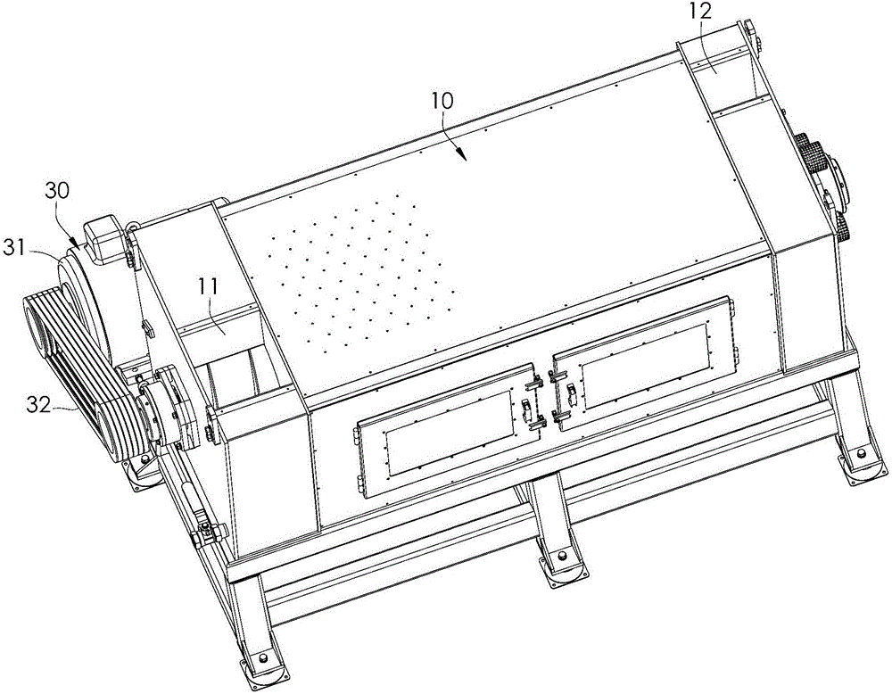
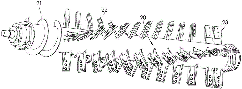
[0023] Such as figure 1 and figure 2 As shown, the friction cleaning machine of the present invention includes a box body 10 and a rotating shaft 20 . A cleaning space is formed inside the box body 10, and a screen is installed on the inside of the cavity. The box body 10 is provided with a feed port 11 and a discharge port 12 communicating with the cleaning space; the rotating shaft 20 is pivotally connected to the box body 10 And be located in this cleaning space; The outer surface of rotating shaft 20 is respectively provided with a continuous helical blade 21, inclined blade 22 assembly and straight blade 23 assembly, and this helical blade 21, inclined blade 22 assembly and straight blade 23 assembly are along the axis of rotating shaft 20 Arranged in sequence; the helical blade 21 extends along the first helical line, the helical blade 21 is lo...


PUM


Abstract

The invention discloses a friction cleaning machine. The friction cleaning machine comprises a box and a rotary shaft. A cleaning space is formed in the box. A screen is mounted on the inner side of a cavity. The box is provided with a feeding port and a discharging port, and the feeding port and the discharging port communicate with the cleaning space. The rotary shaft is pivoted to the box and located in the cleaning space. A continuous spiral blade, oblique blade assemblies and straight blade assemblies are sequentially arranged on the outer surface of the rotary shaft in the axial direction of the rotary shaft. The spiral blade is located in the position of the feeding port and used for conveying materials entering the cleaning space from the feeding port to the oblique blade assemblies. The oblique blade assemblies are used for scattering the materials and making the materials rub with the screen, so that dirt adhering to the materials falls and is thrown out of the screen. The straight blade assemblies are located in the position of the discharging port and used for throwing the materials out from the discharging port. The friction cleaning machine is good in cleaning effect, and power is strong during discharging so that the materials can be conveyed to the next station conveniently.

Description

technical field [0001] The present invention relates to friction cleaning machines. Background technique [0002] When recycling materials, since dirt (such as sand and dust) will adhere to the materials, it is necessary to use a friction cleaning machine to clean the materials. The net rubs, so that the dirt of the material falls off. [0003] It is difficult for the existing friction cleaning machine to spread the material during work, resulting in poor cleaning effect, and the existing friction cleaning machine generally has insufficient power to discharge the material, so it is difficult to send the material to the next station. Contents of the invention [0004] In order to overcome the deficiencies of the prior art, the object of the present invention is to provide a friction cleaning machine with better cleaning effect and greater power when discharging, so that the material can be sent to the next station conveniently. [0005] The object of the present invention...

Claims


Application Information

Patent Timeline
Patent Type & Authority Applications(China)
IPC IPC(8): B08B7/00B07B1/46
CPCB08B7/00B07B1/4609
Inventor 蒋经发
Owner GENOX RECYCLING TECH
Why Eureka
Try Eureka