Shaping device of thin-walled rotary piece

A thin-walled rotary and shaping device technology, which is applied in the field of thin-walled workpiece processing of rotary bodies, can solve the problems of insufficient cutting, easy spring back to original shape, and many auxiliary man-hours.

Inactive Publication Date: 2017-01-04
ANHUI WANNAN ELECTRIC MACHINE
View PDF15 Cites 2 Cited by
  • Summary
  • Abstract
  • Description
  • Claims
  • Application Information

AI Technical Summary

Problems solved by technology

There are many problems in this processing method: it is prone to the phenomenon of knife edge and cutting not in place, and it does not solve the problem of non-concentricity of the two ends of the mouth; after the seam is processed, it is easy to spring back to the original shape, and it must be tested for at least one knife, and then adjusted to assist More working hours and low efficiency

Method used


Image

  • Shaping device of thin-walled rotary piece
  • Shaping device of thin-walled rotary piece
  • Shaping device of thin-walled rotary piece

Examples


Embodiment Construction

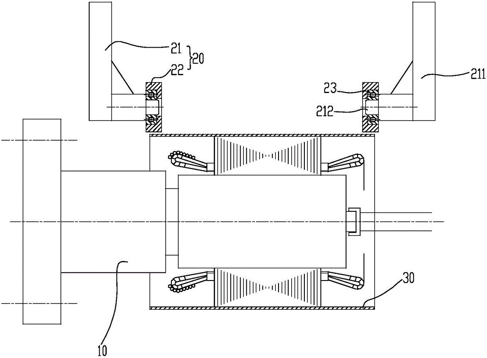
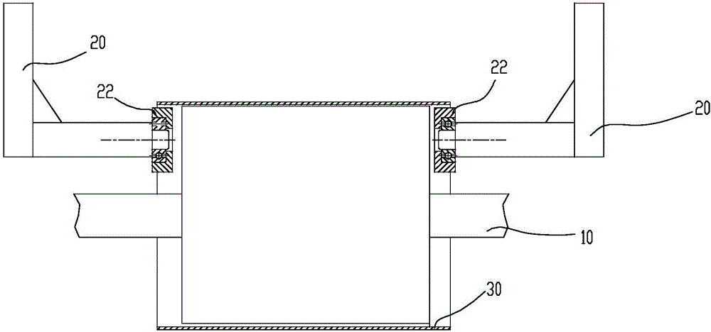
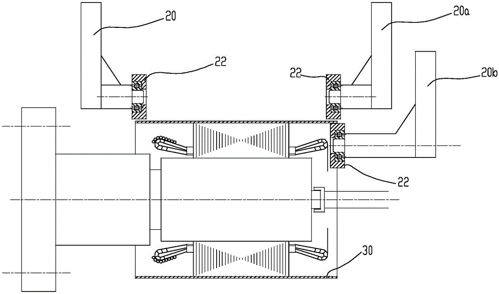
[0009] A shaping device for a thin-walled rotary part, comprising a rotating shaft 10 for fixing and driving a thin-walled rotary part 30 to rotate. Unit 20, the shaping unit 20 includes a bracket 21 and a shaping ring 22 fixed on the bracket 21, the axis of the shaping ring 22 is parallel to the axis of the rotating shaft 10, and the distance between the shaping ring 22 and the axis of the rotating shaft 10 is equal to the thin-walled The theoretical turning radius of the rotating member 30 and the sum of the radii of the shaping ring 22 or the difference of half of the radii. Specifically means: the distance between the shaping ring 22 and the axis of the rotating shaft 10=theoretical turning radius of the thin-walled rotary part 30+the radius of the shaping ring 22, in this case the shaping unit 20 is used to trim the outer circle of the thin-walled rotary part 30 or the distance between the shaping ring 22 and the axis of the rotating shaft 10=theoretical turning radius of...


PUM


Abstract

The invention relates to the field of rotary body thin-walled workpiece machining, in particular to a shaping device of a thin-walled rotary piece. The shaping device comprises a rotary shaft used for fixing the thin-walled rotary piece and driving the thin-walled rotary piece to rotate. The rotation central line of the thin-walled rotary piece coincides with the axis of the rotary shaft. A shaping unit is arranged beside the rotary shaft. The shaping unit comprises a support and a shaping ring fixed to the support. The axis of the shaping ring is parallel to the axis of the rotary shaft. The distance between the shaping ring and the axis of the rotary shaft is equal to the sum or difference of the theoretical rotation radius of the thin-walled rotary piece and the radius of the shaping ring. In the process that the rotary shaft drives the thin-walled rotary piece to rotate, the shaping ring continuously squeezes the pipe wall, with too large or too small rotation radius, of the thin-walled rotary piece, so that the outer wall of the part contracts inwards or expands outwards, the oval section of the thin-walled rotary piece is trimmed to be circular, the roundness of the thin-walled rotary piece is corrected rapidly and effectively, and the quality of the thin-walled rotary piece is improved.

Description

technical field [0001] The invention relates to the field of processing thin-walled workpieces of rotary bodies, in particular to a shaping device for thin-walled rotary parts. Background technique [0002] Thin-walled rotary parts refer to parts such as cylinders and cones. The roundness refers to the radius difference between two concentric circles with the same cross-section actual contour and the radius difference is the smallest. Because the cylinder wall of this kind of parts is thin, it is easy to deform, and the roundness of the cylinder wall is poor, which affects the subsequent use. [0003] The thin-walled stainless steel motor frame is a thin-walled rotating part. The thin-walled stainless steel motor frame is generally made of 2mm thick stainless steel plate folded and welded, and the two ends are processed after being pressed into the stator core. During the press-in process of the stator core, uneven force at both ends of the machine base is prone to irregula...

Claims


Application Information

Patent Timeline
Patent Type & Authority Applications(China)
IPC IPC(8): B21D1/08
CPCB21D1/08
Inventor 柯磊管华汪军吴丹方星耀蒋小兵
Owner ANHUI WANNAN ELECTRIC MACHINE
Why Eureka
Try Eureka