
scoring device

A technology for scribing lines and substrates, applied in the field of scribing devices, can solve problems such as troublesome alignment operations, and achieve the effect of efficient and high-precision scribing

Active Publication Date: 2021-09-03
MITSUBOSHI DIAMOND IND CO LTD
View PDF11 Cites 0 Cited by
  • Summary
  • Abstract
  • Description
  • Claims
  • Application Information

AI Technical Summary

Problems solved by technology

However, this position alignment work is very troublesome, and in order to perform this position alignment work with high precision, a highly skilled technique is required

Method used


Image

  • scoring device
  • scoring device
  • scoring device

Examples


Embodiment Construction

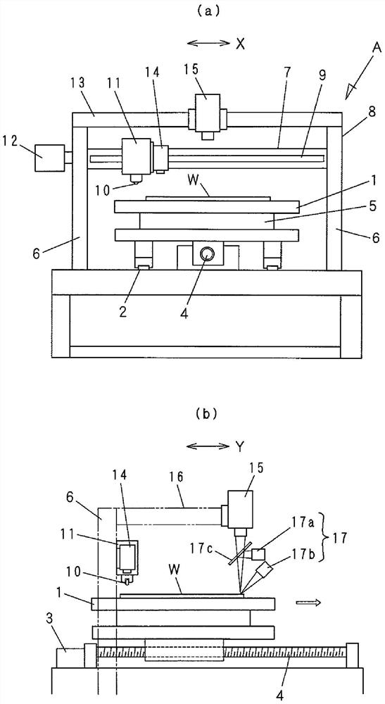
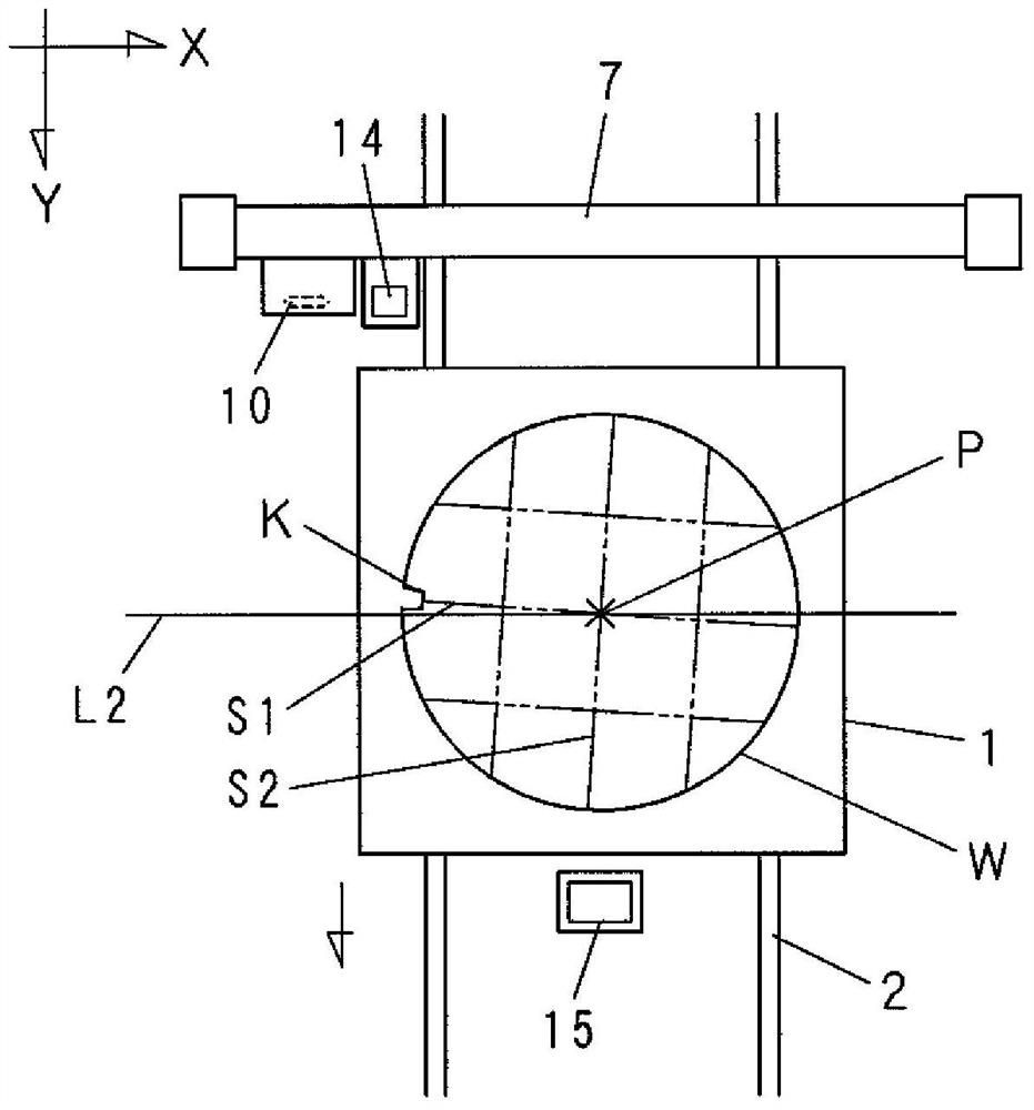
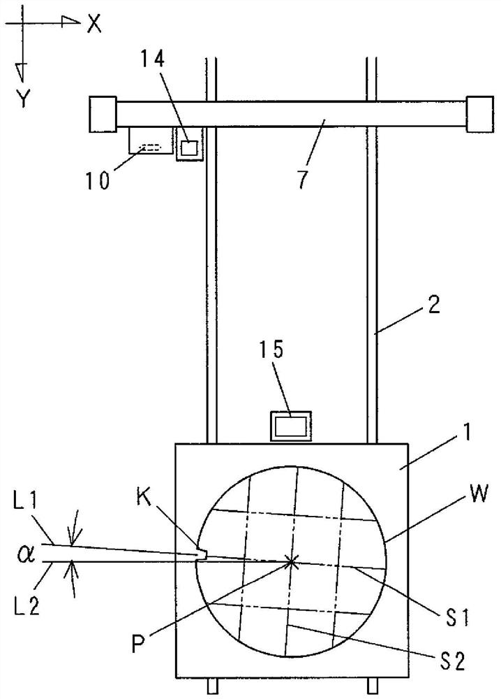
[0032] Hereinafter, the present invention will be described in detail based on the embodiments shown in the drawings. The circular substrate to be scribed in this embodiment is a semiconductor substrate W for an image sensor in which a glass wafer and a silicon wafer are laminated. Such as figure 2 As shown, chips including electronic components such as circuits are arranged in a grid pattern on the semiconductor substrate W, and lines in the X-Y direction that divide these chips form predetermined scribing lines (scribing lanes) S1 and S2 . Moreover, on any one of the predetermined scribe lines passing through the center point P of the semiconductor substrate W, in this embodiment, on the predetermined scribe line S1, and on the edge of the semiconductor substrate W, a notch or a positioning plane is provided as a mark. The incision part K.

[0033] figure 1 (a) and (b) show an embodiment of the scribing apparatus A of the present invention, which includes a stage 1 on w...


PUM


Abstract

The present invention provides a scribing apparatus capable of automatically and accurately correcting the inclination of a circular substrate placed on a table. A scribing device (A) for placing a circular substrate (W) on a rotatable table (1), and using a cutter wheel (10) or a laser along a predetermined scribing line (S1, S2) on the surface Scribing is performed to form a splitting crack, wherein a notch is formed on the edge of the circular substrate (W) on a line parallel to the planned scribe lines (S1, S2) and passing through the center point (P) of the circle Part (K), the scribing device (A) includes a control part (18) of a computer (C), the control part (18) is capable of observing the circular substrate (W) placed on the table (1) The angle correction for detecting the outer shape is analyzed with the image data obtained by the camera (15), thereby detecting the scribing of the predetermined scribing lines (S1, S2) of the circular substrate (W) with respect to the cutter wheel (10). The inclination angle (α) of the direction, the table (1) is rotated so that the inclination angle (α) is zero.

Description

technical field [0001] The present invention relates to a scribing device for processing and dividing fissures (cracks) on circular substrates made of brittle materials such as glass, silicon, ceramics, and compound semiconductors. In particular, the present invention relates to a scribing apparatus for processing cracks for dividing unit products such as chips from a circular semiconductor substrate (semiconductor wafer). Background technique [0002] Usually, in the process of cutting out chips (unit products) from a semiconductor substrate as a mother board, first, the semiconductor substrate is placed on the suction table of the scribing device, and the surface is scribed along a predetermined line with a cutter wheel or a laser. Lines (scribed lanes) are scribed to form scribed lines (cracks) in the X-direction and Y-direction orthogonal to each other. Thereafter, the semiconductor substrate is divided into square chips by pressing the cutting lever from the surface op...

Claims


Application Information

Patent Timeline
Patent Type & Authority Patents(China)
IPC IPC(8): B25H7/04
CPCB25H7/04
Inventor 栗山规由青木仁宏吉田圭吾
Owner MITSUBOSHI DIAMOND IND CO LTD
Learn More