Art knife

A utility knife and knife holder technology, which is applied in metal processing, artist hand tools, decorative arts, etc., can solve the problems of inconvenient operation, blade falling out of the utility knife, doubts about the use of safety, etc., and achieve the effect of convenient operation

Active Publication Date: 2017-01-04
顺德工业(江苏)有限公司
View PDF6 Cites 11 Cited by
  • Summary
  • Abstract
  • Description
  • Claims
  • Application Information

AI Technical Summary

Problems solved by technology

[0005] 1. Inconvenient operation: Both hands are required to lock or loosen the bolts, and when moving the blade, the bolt must be loosened before the regulator can be moved. After the blade position is adjusted, the bolt must be locked before it can be used. Therefore, the locking process of the existing utility knife is cumbersome, which makes the operation inconvenient
[0006] 2. Use safety concerns: When the blade is not clamped by the upper and lower tool holders, since the blade is

Method used


Image

  • Art knife
  • Art knife
  • Art knife

Examples


Embodiment Construction

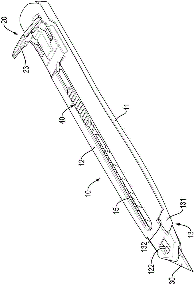
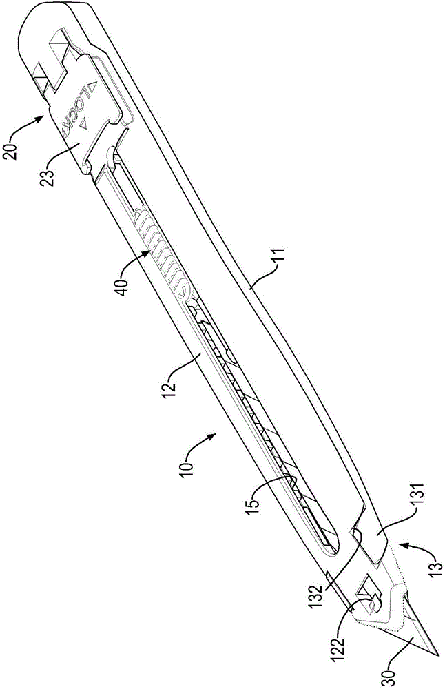
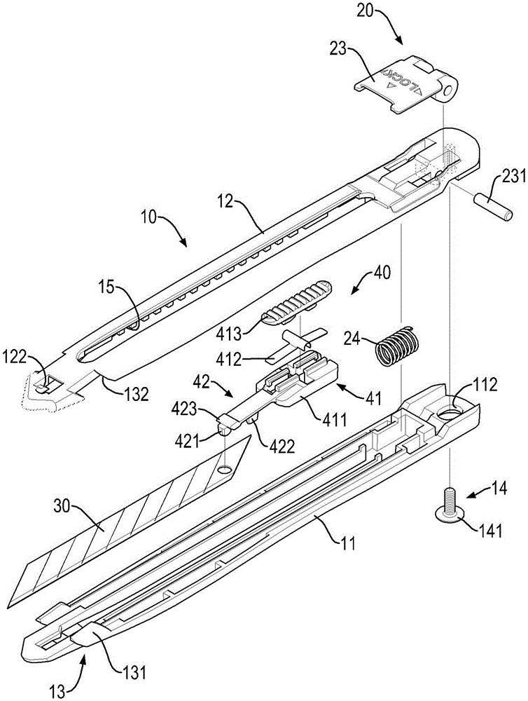
[0044] see Figure 1 to Figure 3 As shown, the utility knife proposed by the present invention includes a blade body 10, a locking structure 20, a blade 30, and a regulator 40. The blade body 10 includes a lower knife seat 11, an upper knife seat 12, and an inclined plane limiting structure 13. 1. The lower knife rests 11 and 12 can move relative to each other, and the bevel limit structure 13 is formed on a front end of the lower knife rest 11 and a front end of the upper knife rest 12, so that the front ends of the upper and lower knife rests 11 and 12 are limited by an inclined plane. The position structure 13 forms an oblique abutment; preferably, the bevel limit structure 13 is a concave-convex matching structure inclined forward from bottom to top, and the bevel limit structure 13 is respectively convexly provided with a Limiting guide blocks 131 are respectively recessed with a limiting guide groove 132 on both sides of the front end of the upper knife seat 12, and each...


PUM


Abstract

The invention provides an art knife. The art knife has the advantage of convenient operation and comprises a knife body, a locking structure, an adjuster movably arranged in the knife body, and a blade connected to the adjuster. The knife body comprises a lower knife holder, an upper knife holder and a bevel limiting structure which makes the lower knife holder and the upper knife holder be abutted against each other obliquely. The lower knife holder and the upper knife holder can move oppositely. The locking structure is arranged one rear end of the knife body and comprises a datum point, a first driving face and a second driving face, and the first driving face or the second driving face is abutted against the upper knife holder or the lower knife holder. The distance from the datum point to the first driving face is a first distance. The distance from the datum point to the second driving face is a second distance. The first distance is larger than the second distance. When the first driving face or the second driving face is abutted against the upper knife holder or the lower knife holder, the upper knife holder and the lower knife holder move oppositely, the front ends of the upper knife holder and the lower knife holder are guided by the bevel limiting structure, and opposite movement is formed correspondingly.

Description

technical field [0001] The invention relates to the technical field of utility knife structure, in particular to a utility knife. Background technique [0002] Please refer to the CN No. 204749686 announcement for the structure of the existing utility knife, which includes a pair of upper and lower knife holders with matching guide grooves and guide blocks at the front ends, one passing through the upper knife holder along the length direction of the upper knife holder and A bolt attached to the lower seat, a set of springs mounted on the bolt and abutted between the upper and lower seats, an adjuster movable between the upper and lower seats, and a blade clamped by the adjuster . [0003] When in use, locking or loosening the bolt allows the upper and lower tool holders to move with each other; The guide groove and the guide block move relatively separately. At this time, the adjuster can be pushed to drive the blade to move in the upper and lower tool holders, and then t...

Claims


Application Information

Patent Timeline
IPC IPC(8): B26B1/08B44B11/00
CPCB26B1/08B44B11/00
Inventor 杜兵峰
Owner 顺德工业(江苏)有限公司
Why Eureka
Try Eureka