Tee joint injection mold

An injection mold and tee technology, which is applied to household appliances, other household appliances, household components, etc., can solve the problems of inability to guarantee the quality of injection molding tee products, unfavorable for wide-scale promotion and use, and difficulty in transporting mold cores back and forth. Achieving stable size, good use effect and labor saving effect

Active Publication Date: 2017-01-04
BAODING TIANYIN MACHINERY
View PDF6 Cites 0 Cited by
  • Summary
  • Abstract
  • Description
  • Claims
  • Application Information

AI Technical Summary

Benefits of technology

This patented technology allows for better control over how much heat it generates during machining processes by allowing certain parts or tools that were previously used without proper temperature management to continue working properly even if they are still hot enough when needed again later on.

Problems solved by technology

This patented describes how injector plates (also called nozzles) made from materials like rubber or silicone have been developed for making small parts such as valves. However, these methods require expensive equipment and take too much time to produce them due to their complicated design. Therefore there has existed an issue where it becomes difficult to efficiently manufacture high-quality product without taking extra effort outdoors when needed.

Method used


Image

  • Tee joint injection mold
  • Tee joint injection mold
  • Tee joint injection mold

Examples


Embodiment Construction

[0032] It should be noted that, in the case of no conflict, the embodiments of the present invention and the features in the embodiments can be combined with each other.

[0033] The present invention will be described in detail below with reference to the accompanying drawings and examples.

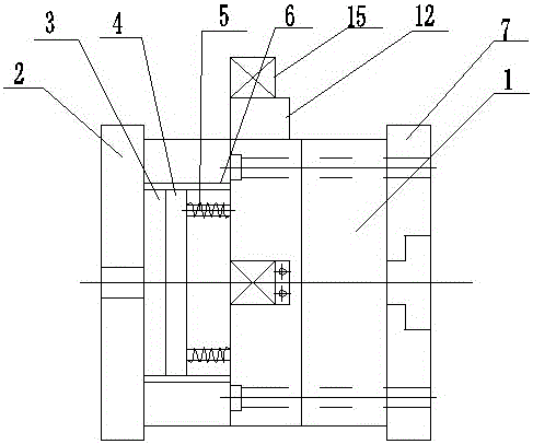
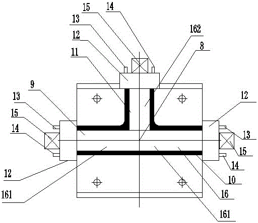
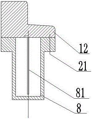
[0034] This embodiment relates to a three-way injection mold. The overall structure includes a fixed mold main body 1, a bottom plate main body 2 is provided on the left side of the fixed mold main body 1, and an ejection bottom plate 3 is provided on the right side of the bottom plate main body 2. The right side of the ejector plate 3 is provided with an ejector plate 4, the right side of the ejector plate 4 is fixed with a return spring 5, the upper and lower sides of the ejector base plate 3 and the ejector plate 4 are provided with ejector rods 6, and the fixed The right side of the mold body 1 is provided with a fixed plate 7; a mold core 8, the mold core 8 includes: a three-way mol...


PUM


Abstract

The invention provides a tee joint injection mold which comprises a stationary mold main body and a mold core, wherein a bottom plate main body is arranged on the left side of the stationary mold main body; a propping bottom plate is arranged on the right side of the bottom plate main body; a propping plate is arranged on the right side of the propping bottom plate; a return spring is fixed on the right side of the propping plate; propping rods are arranged on the upper sides and the lower sides of the propping bottom plate and the propping plate; a fixing plate is arranged on the right side of the stationary mold main body; the mold core comprises a tee joint mold core I, a tee joint mold core II and a tee joint mold core III; the tee joint mold core I is arranged on the right side inside the stationary mold main body; the tee joint mold core II is arranged on the left side inside the stationary mold main body; the tee joint mold core III is arranged on the upper side inside the stationary mold main body; a partitioning plate is arranged inside the mold core. By adopting the tee joint injection mold, machine tool cooling circulation molding can be achieved, a product is already cooled and molded after being taken out from an injection molding machine tool and is stable in size, the product quality is improved, the production cost is reduced, the production efficiency is improved, the operation is simple, the labor is saved, and a very good use effect can be achieved.

Description


Claims


Application Information

Patent Timeline
Owner BAODING TIANYIN MACHINERY
Why Eureka
Try Eureka