Tibia implant for tightening the patella tendons

a technology of tibia implants and patella tendons, which is applied in the field of tibia implants for tightening the patella tendons, can solve the problems of only being poorly connected or anchored to the bone, the implant is much too filigree, and is not able to absorb forces very quickly, so as to prevent the shifting of the tibia implant on the bone, facilitate the rapid growth of the tibia implant, and facilitate the manufacturing process. rapid

Active Publication Date: 2013-01-31
RITA LEIBINGER
View PDF7 Cites 35 Cited by
  • Summary
  • Abstract
  • Description
  • Claims
  • Application Information

AI Technical Summary

Benefits of technology

[0017]These spikes penetrate into the bone surface and prevent a shifting of the tibia implant on the bone. The spikes are smaller in the region of the wedge cut and and/or protrude less out of the sponge structure than on the opposing wider end. Very high forces can be absorbed preferably in that the spikes extend from a sponge structure through the implant and its internal space to the other sponge structure and protrude outwardly over the latter so that the forces can be transferred from the tibia ...

Problems solved by technology

However, it has proven disadvantageous in this case that the implant is much too filigree and incapable of a...

Method used


Image

  • Tibia implant for tightening the patella tendons
  • Tibia implant for tightening the patella tendons
  • Tibia implant for tightening the patella tendons

Examples


Embodiment Construction

[0030]Throughout all the Figures, same or corresponding elements are generally indicated by same reference numerals. These depicted embodiments are to be understood as illustrative of the invention and not as limiting in any way. It should also be understood that the drawings are not necessarily to scale and that the embodiments are sometimes illustrated by graphic symbols, phantom lines, diagrammatic representations and fragmentary views. In certain instances, details which are not necessary for an understanding of the present invention or which render other details difficult to perceive may have been omitted.

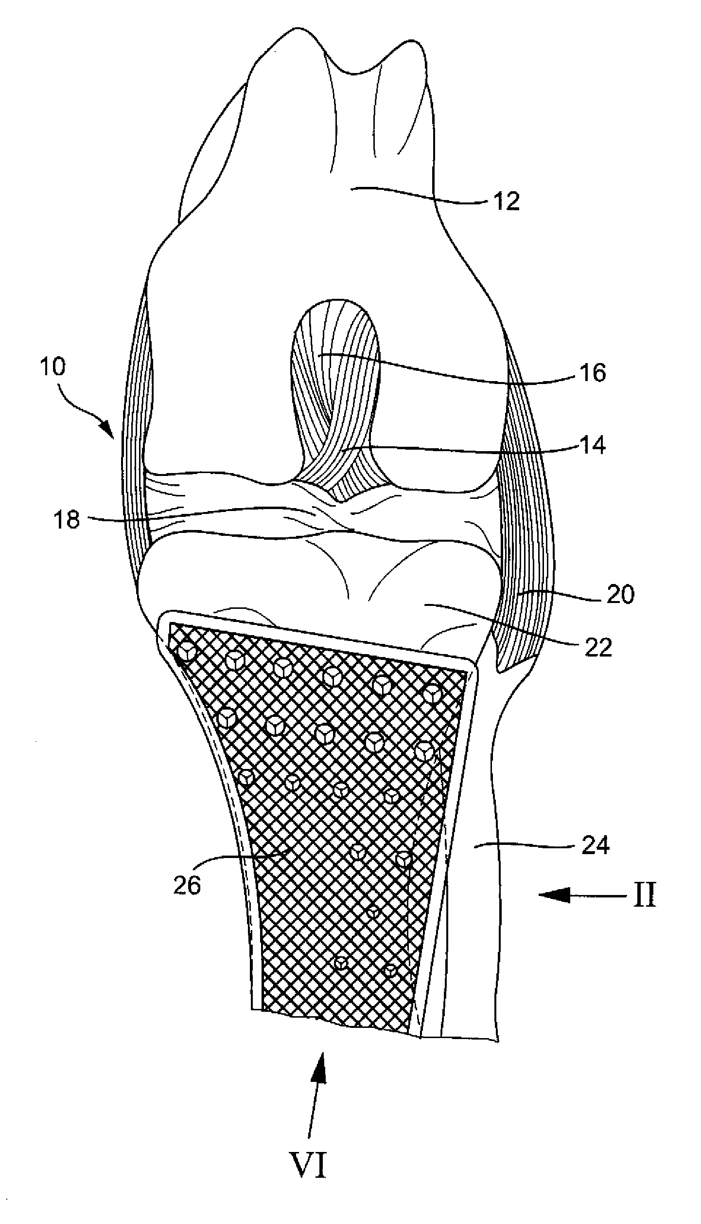
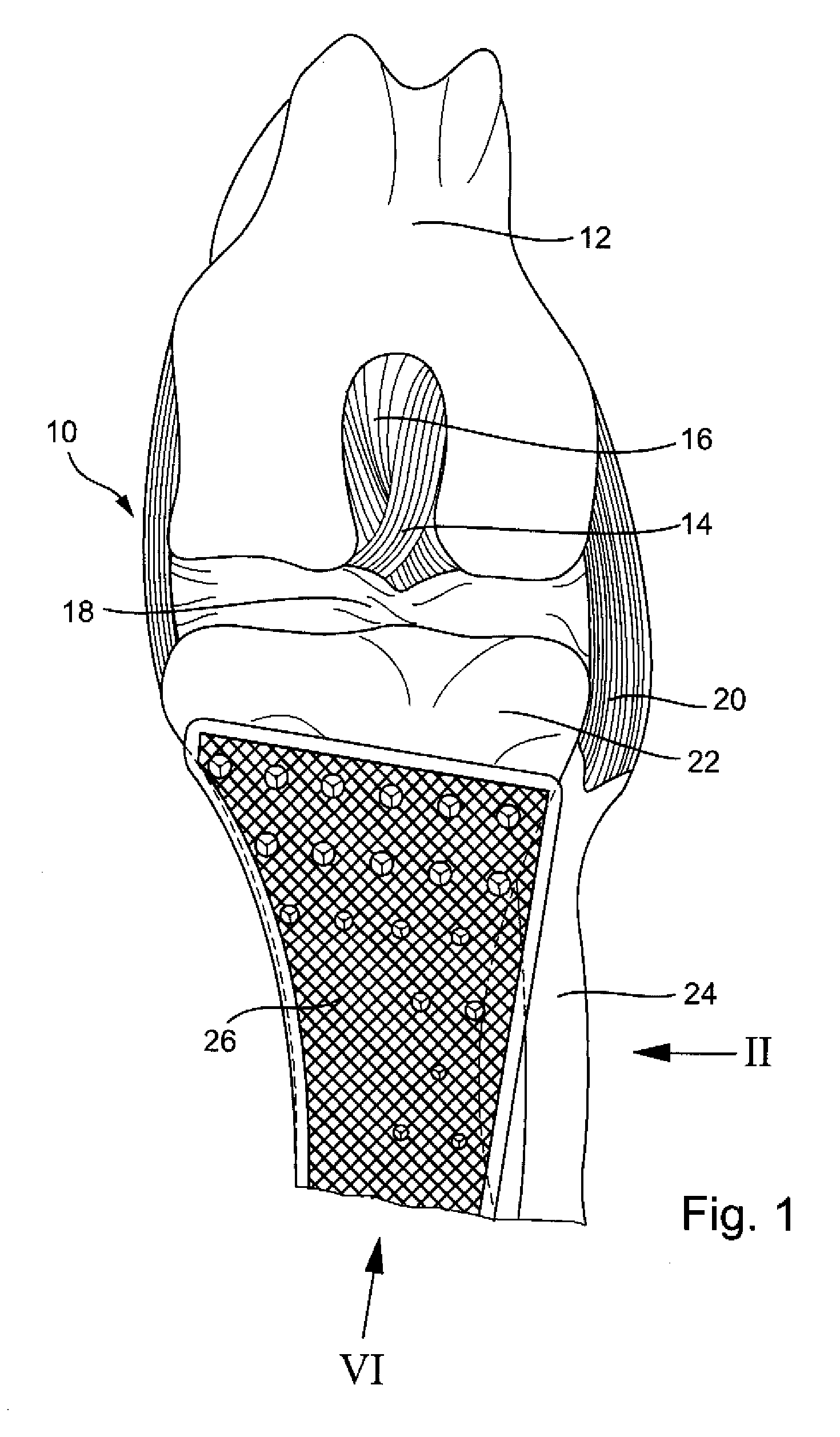
[0031]Turning now to the drawing, and in particular to FIG. 1, there is shown a front view onto a front side of a knee 10, in particular the lower end of the femur 12. The anterior cruciate ligament 14 and the posterior cruciate ligament 16 as well as the menisci 18 and the collateral ligament 20 are shown schematically. Beside the tibia 22, the fibula 24 can be seen. A tibia ...


PUM

PropertyMeasurementUnit
Massaaaaaaaaaa
Structureaaaaaaaaaa
Sizeaaaaaaaaaa

Abstract

A tibia implant for tightening the patella tendons, has a vertical cross section which in mounted position tapers downward, an essentially vertically arranged base plate which carries a sponge structure, wherein the sponge structure on both sides rests against a respective vertical cut surface of a vertical knee proximal incision of the tibia.

Description

CROSS-REFERENCES TO RELATED APPLICATIONS[0001]This application claims the benefit of prior filed U.S. provisional Application No. 61 / 511,577, filed Jul. 26, 2011, pursuant to 35 U.S.C. 119(e), the disclosure of which is incorporated herein by reference.BACKGROUND OF THE INVENTION[0002]The present invention relates to a tibia implant for tightening the patella tendons[0003]The following discussion of related art is provided to assist the reader in understanding the advantages of the invention, and is not to be construed as an admission that this related art is prior art to this invention.[0004]From US 2010 / 0076564 an implant has become known with which in particular in the veterinary medicine the tendons of a knee can be tightened again. For this, the tibia is split from above in the knee proximal region so that a wedge shaped incision is created. However, the tibia section must not be cleaved off completely. The implant is inserted into the incision so that the tibia section is brac...

Claims


Application Information

Patent Timeline
IPC IPC(8): A61F2/38B23P11/00
CPCA61F2/28A61F2002/2835A61F2002/2892Y10T29/49908A61F2002/30841A61F2002/3092A61B17/8061A61F2002/30576
Inventor LEIBINGER, RITA
Owner RITA LEIBINGER
Why Eureka
Try Eureka