An elevator speed limiter

A technology of elevator speed limiter and rope wheel, which is applied in elevators, transportation and packaging, etc. It can solve the problems of ratchets and ratchets not meshing, and achieve the effects of ensuring trigger sensitivity, reliable work, and enhancing centrifugal force

Inactive Publication Date: 2018-06-19
YICHUN SPECIAL EQUIP SUPERVISION & INSPECTION CENT
View PDF11 Cites 1 Cited by
  • Summary
  • Abstract
  • Description
  • Claims
  • Application Information

AI Technical Summary

Problems solved by technology

[0003] Existing elevator speed governors use springs to pull the centrifugal block or centrifugal rod, but the elasticity of the springs will change after repeated use or long-term placement, resulting in the ratchet not meshing with the ratchet in the event of an accident, or the sheave The centrifugal rod or the centrifugal block has been released before the speed exceeds the speed

Method used


Image

  • An elevator speed limiter
  • An elevator speed limiter

Examples


Embodiment 1

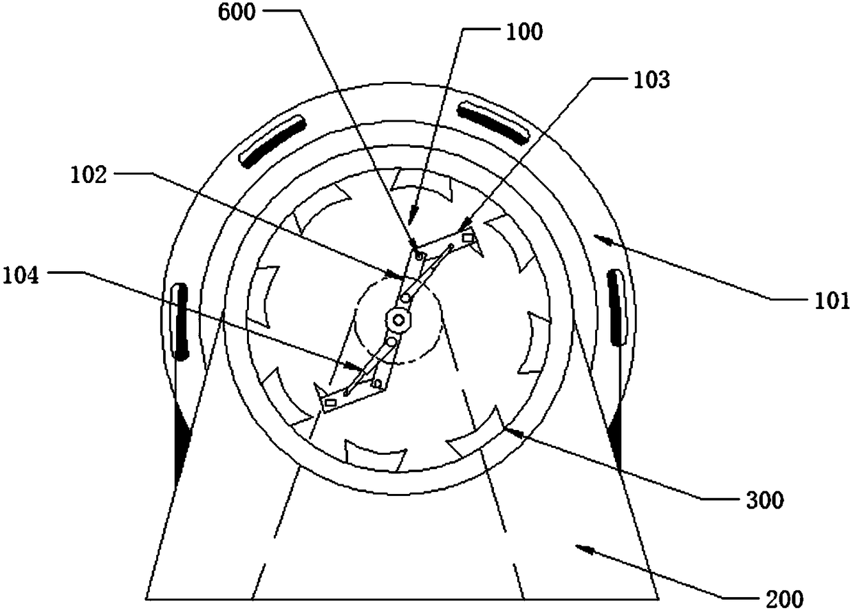
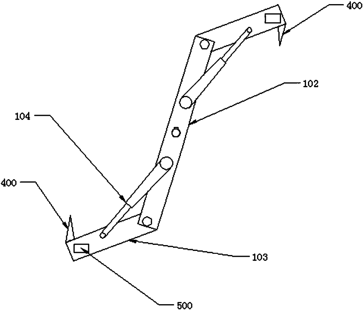
[0033] Such as Figure 1-Figure 2 As shown, a speed governor of an elevator includes a sheave part 100, a frame 200 and a ratchet 300 fixedly connected with the frame, and the sheave part 100 includes a sheave 101, a centrifugal rod 103 and a main rod 102. The middle part of main rod 102 is fixedly installed in the center of rope wheel 101, and described rope wheel 101 is installed on the frame 200 through bearing, and described rope wheel 101 and ratchet 300 are concentric; The two ends of described main rod 102 are hinged respectively The centrifugal rod 103, and the main rod 102 on both sides of the center of the sheave 101 are respectively connected to a self-locking hydraulic rod 104, and the other end of the self-locking hydraulic rod 104 is connected to the middle part of the centrifugal rod 103, and the centrifugal rod 103 is away from The end of the main rod 102 is fixedly connected with a ratchet 400 corresponding to the ratchet wheel 300 .

Embodiment 2

[0035] Such as Figure 1-Figure 2 As shown, a speed governor of an elevator includes a sheave part 100, a frame 200 and a ratchet 300 fixedly connected with the frame, and the sheave part 100 includes a sheave 101, a centrifugal rod 103 and a main rod 102. The middle part of main rod 102 is fixedly installed in the center of rope wheel 101, and described rope wheel 101 is installed on the frame 200 through bearing, and described rope wheel 101 and ratchet 300 are concentric; The two ends of described main rod 102 are hinged respectively The centrifugal rod 103, and the main rod 102 on both sides of the center of the sheave 101 are respectively connected to a self-locking hydraulic rod 104, and the other end of the self-locking hydraulic rod 104 is connected to the middle part of the centrifugal rod 103, and the centrifugal rod 103 is away from The end of the main rod 102 is fixedly connected with a ratchet 400 corresponding to the ratchet wheel 300 .

[0036] A positioning pi...

Embodiment 3

[0038] Such as Figure 1-Figure 2 As shown, a speed governor of an elevator includes a sheave part 100, a frame 200 and a ratchet 300 fixedly connected with the frame, and the sheave part 100 includes a sheave 101, a centrifugal rod 103 and a main rod 102. The middle part of main rod 102 is fixedly installed in the center of rope wheel 101, and described rope wheel 101 is installed on the frame 200 through bearing, and described rope wheel 101 and ratchet 300 are concentric; The two ends of described main rod 102 are hinged respectively The centrifugal rod 103, and the main rod 102 on both sides of the center of the sheave 101 are respectively connected to a self-locking hydraulic rod 104, and the other end of the self-locking hydraulic rod 104 is connected to the middle part of the centrifugal rod 103, and the centrifugal rod 103 is away from The end of the main rod 102 is fixedly connected with a ratchet 400 corresponding to the ratchet wheel 300 .

[0039] A positioning pi...


PUM


Abstract

The invention discloses an elevator speed governor which comprises a rope sheave part, a machine frame and a ratchet wheel fixedly connected with the machine frame. The rope sheave part comprises a rope sheave, a centrifugal rod and a main rod. The middle of the main rod is fixedly installed in the center of the rope sheave, the rope sheave is installed on the machine frame through a bearing, and the rope sheave and the ratchet wheel are concentric; the two ends of the main rod are both provided with a centrifugal rod in a hinged mode, the portions, on the two sides of the center of the rope sheave, of the main rod are both provided with a self-locking hydraulic rod, the other end of each self-locking hydraulic rod is connected with the middle of the centrifugal rod, and a ratchet is fixedly connected with the end, away from the main rod, of the centrifugal rod and corresponds to the ratchet wheel.

Description

technical field [0001] The invention relates to an elevator safety device, in particular to an elevator speed governor. Background technique [0002] Existing elevator speed limiting protection devices all drive the safety gear of the braking device to act through the speed governor, so that the elevator decelerates and stops. The speed governor includes a sheave on which a wire rope connected to the elevator car is wound, so that the speed governor sheave can rotate at a speed corresponding to the speed of the car. The wire rope on the rope wheel connects the safety gear. When the rotation speed of the speed limiter sheave exceeds a certain speed, the centrifugal throwing block on the speed limiter sheave rotates with the help of the centrifugal force generated by the rotation of the sheave, driving the pressure claw and pawl on the sheave to move, so that the speed limiter The rope pressing block in the rope pressing part on the device presses the wire rope, the wire rop...

Claims


Application Information

Patent Timeline
Patent Type & Authority Patents(China)
IPC IPC(8): B66B5/16
CPCB66B5/16
Inventor 刘飞袁超
Owner YICHUN SPECIAL EQUIP SUPERVISION & INSPECTION CENT
Why Eureka
Try Eureka