Blower

A blower and air duct technology, which is applied in gardening, botany equipment and methods, road cleaning, etc., can solve the problems of unreasonable structure setting and inability to guarantee the blowing efficiency of the blower, and achieve the effect of reasonable structure setting and guaranteed air intake efficiency

Active Publication Date: 2017-01-04
NANJING CHERVON IND
View PDF7 Cites 5 Cited by
  • Summary
  • Abstract
  • Description
  • Claims
  • Application Information

AI Technical Summary

Problems solved by technology

[0004] However, the structure setting of the existing linear air duct is unreasonable, and the position of the air inlet often cannot guarantee the blowing efficiency of the hair dryer.

Method used


Image

  • Blower
  • Blower
  • Blower

Examples


Embodiment Construction

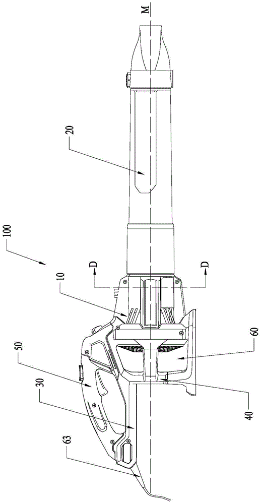
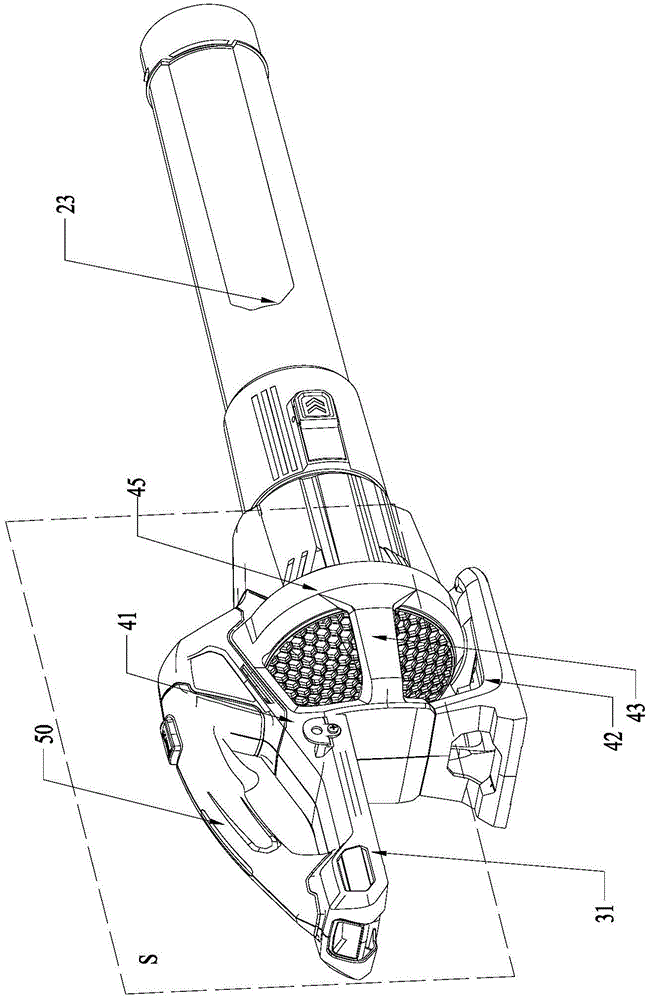
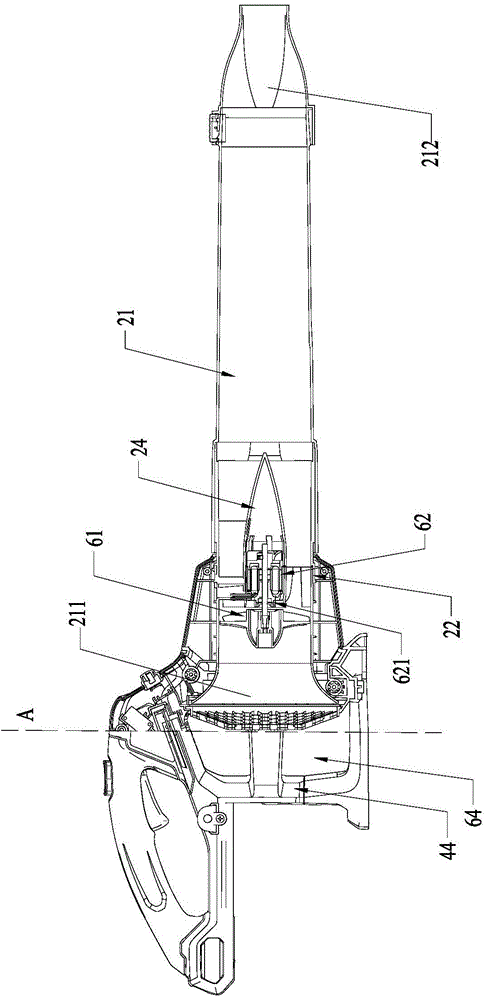
[0052] Such as Figure 1 to Figure 3 The blower 100 shown in the first embodiment includes a casing 10 , a fan 61 and a prime mover 62 , wherein the fan 61 is accommodated in the casing 10 , and the prime mover 62 is used to drive the fan 61 to rotate around the central axis M to generate air flow. In order to guide the airflow generated by the fan 61, the casing 10 is formed with an air duct portion 20, and the air duct portion 20 is formed with an air duct 21 extending approximately along the central axis M, and the air duct 21 is used to guide the air flow from the air duct 21 The channel inlet 211 flows to the air channel outlet 212 . As a specific solution, the fan 61 is disposed in the air duct 21 of the air duct portion 20 , and the air duct inlet 211 and the air duct outlet 212 are respectively disposed at opposite ends of the air duct 21 along the central axis M direction.

[0053] For convenience of description, below, the side of the air duct inlet 211 is referred ...


PUM


Abstract

The invention discloses a blower comprising a housing, a fan and a prime motor. The fan is accommodated into the housing; the prime motor drives the fan to rotate surrounding a center axis; the housing is formed by an air channel part, an energy input part and a middle part; the air channel part forms an air channel extending basically along the center axis; the energy input part introduces energy in an energy device supplying power to the prime motor to the housing; the middle part is placed between the air channel part and the energy input part; the prime motor is accommodated into the air channel; opposite ends of the air channel are respectively provided with an air channel inlet and an air channel outlet; the air channel inlet is formed between the prime motor and the energy input part; and the middle part forms an air inlet enabling air flows passing through the housing. The blower has rational structure and great air blowing efficiency.

Description

technical field [0001] The invention relates to a garden tool, in particular to a hair dryer. Background technique [0002] A hair dryer is a commonly used garden tool, which can help users use airflow to clean up fallen leaves in the garden. Existing hair dryers are divided into centrifugal hair dryers and axial flow hair dryers. Among them, the axial flow hair dryer can generate a larger air volume to make it more suitable for the needs of users. [0003] The blower generates the required air flow through the air duct and the fan arranged in the air duct. In order to achieve a better blowing effect, the air duct structure is preferably designed as a linear air duct. [0004] However, the structure setting of the existing linear air duct is unreasonable, and the position of the air inlet often cannot guarantee the blowing efficiency of the hair dryer. Contents of the invention [0005] In order to solve the deficiencies of the prior art, the object of the present inven...

Claims


Application Information

Patent Timeline
Patent Type & Authority Applications(China)
IPC IPC(8): E01H1/08A01G1/12
Inventor 郭建朋聂方杰
Owner NANJING CHERVON IND
Why Eureka
Try Eureka