Accurate and comprehensive monitoring carbon emission monitoring system based on Internet of Things and use method thereof
A monitoring system and carbon emission technology, applied in separation methods, chemical instruments and methods, measuring devices, etc., can solve problems affecting carbon emission monitoring efficiency, affecting air intake rate, and unable to monitor carbon dioxide, so as to improve accuracy and improve Comprehensiveness, the effect of improving uniformity
- Summary
- Abstract
- Description
- Claims
- Application Information
AI Technical Summary
Problems solved by technology
Method used
Image
Examples
Embodiment 1
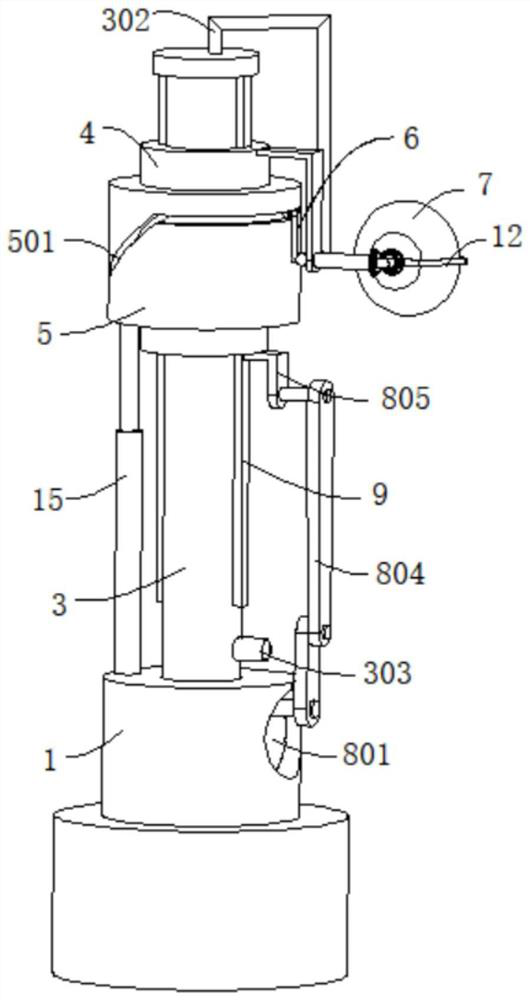
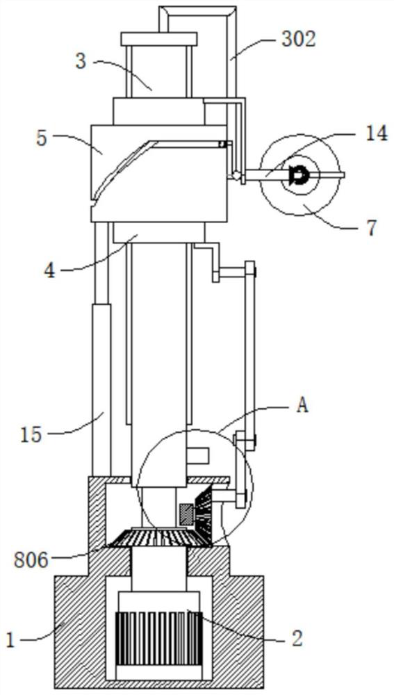
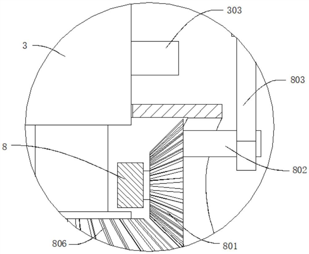
[0040] refer to figure 1 , figure 2 , Figure 4 , Figure 5 and Figure 10 , a carbon emission monitoring system based on accurate and comprehensive monitoring of the Internet of Things, including a base 1, a driving motor 2 is arranged inside the base 1, a rotating rod 3 is connected to the output end of the driving motor 2, and the end of the rotating rod 3 away from the driving motor 2 is worn through Through the base 1 and extending outward, the rotating rod 3 is provided with a monitoring component, the outer wall of the rotating rod 3 is slidingly connected to the moving tube 4, the base 1 is provided with a lifting mechanism for driving the moving tube 4 to move up and down, and the moving tube 4 is provided with The fixed plate 401, the outer wall of the moving tube 4 is also rotatably connected with a casing 5, the telescopic rod 15 is fixedly connected between the casing 5 and the base 1, the outer wall of the casing 5 is provided with a track groove 501, and mov...
Embodiment 2
[0043] refer to figure 1 , figure 2 , Figure 5 , Figure 7 , Figure 8 and Figure 9 , a carbon emission monitoring system based on accurate and comprehensive monitoring of the Internet of Things, which is the same as Embodiment 1, furthermore, the movable part 6 includes a ball 601 slidingly connected in the track groove 501, and the ball 601 is movably provided with a first connection Rod 602, the end of the first connecting rod 602 away from the ball 601 is fixedly connected with a connecting plate 603, the connecting plate 603 is fixedly connected with an L-shaped tube 604, the L-shaped tube 604 is connected with the monitoring component, and the L-shaped tube 604 is far away from the connecting plate 603 One end communicates with the air intake bucket 7.
[0044] Specifically, by controlling the operation of the driving motor 2, the output end of the driving motor 2 drives the rotating rod 3 to rotate, and then the rotating rod 3 drives the moving tube 4 to rotate ...
Embodiment 3
[0046] refer to figure 1 , figure 2 , image 3 , Figure 4 and Figure 10 , a carbon emission monitoring system based on the accurate and comprehensive monitoring of the Internet of Things, which is the same as Embodiment 2, and furthermore, the monitoring component includes a monitoring cavity 301 set in the rotating rod 3, and the two ends of the monitoring cavity 301 are respectively connected with advanced The air pipe 302, the air outlet pipe 303, the air inlet pipe 302 and the L-shaped pipe 604 communicate with each other, and the monitoring assembly also includes a fan 304 fixed in the monitoring chamber 301 and a monitoring sensor 305 for monitoring the carbon dioxide concentration.
[0047] Specifically, when the device is working, by controlling the operation of the blower fan 304 in the monitoring chamber 301, the blower fan 304 can suck the outside air through the air intake pipe 302 and the air intake bucket 7 connected with the air intake pipe 302, so that th...
PUM
 Abstract
Description
Claims
Application Information
 - R&D
- Intellectual Property
- Life Sciences
- Materials
- Tech Scout
- Unparalleled Data Quality
- Higher Quality Content
- 60% Fewer Hallucinations
Browse by: Latest US Patents, China's latest patents, Technical Efficacy Thesaurus, Application Domain, Technology Topic, Popular Technical Reports.
© 2025 PatSnap. All rights reserved.Legal|Privacy policy|Modern Slavery Act Transparency Statement|Sitemap|About US| Contact US: help@patsnap.com


