Clamping device for steel pipe concrete member with specially-shaped section

A technology of steel pipe concrete and clamping device, which is applied in the field preparation of building components, building structure, formwork/formwork/working frame, etc. Fixing gaps, affecting the structure of steel pipe concrete, etc., to achieve the effect of no gaps and firm clamping, preventing clamping loosening, and easy operation

Active Publication Date: 2017-01-04
SICHUAN UNIV
View PDF5 Cites 7 Cited by
  • Summary
  • Abstract
  • Description
  • Claims
  • Application Information

AI Technical Summary

Problems solved by technology

[0002] With the development of society and the prosperity of the construction industry, the concrete-filled steel tube structure is indispensable in construction engineering, but the pouring of the concrete-filled steel tube structure requires an external clamping device to clamp it, which is convenient for the stability of the concrete-filled steel tube pouring. To improve the ornamental value, the concrete-filled steel tube structure will have some special-shaped sections, and the existing clamping device is not suitable for clamping the special-shaped section concrete-filled steel tube, and the clamping is unstable. device
[0003] At present, there are some deficiencies in the clamping device for concrete-filled steel tube members with special-shaped cross-section. When clamping the concrete-filled steel tube with special-shaped cross-section, the clamping device is operated in one direction by pulling up or pressing down, which is prone to reverse operation, resulting in loosening of the clamping device. It will affect the pouring of concrete filled steel pipe. The existing clamping devices for concrete filled steel tube members with special-shaped cross-sections are all single-layer clamping structures.

Method used


Image

  • Clamping device for steel pipe concrete member with specially-shaped section
  • Clamping device for steel pipe concrete member with specially-shaped section
  • Clamping device for steel pipe concrete member with specially-shaped section

Examples


Embodiment Construction

[0018] The following will clearly and completely describe the technical solutions in the embodiments of the present invention with reference to the accompanying drawings in the embodiments of the present invention. Obviously, the described embodiments are only some, not all, embodiments of the present invention. Based on the embodiments of the present invention, all other embodiments obtained by persons of ordinary skill in the art without making creative efforts belong to the protection scope of the present invention.

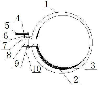
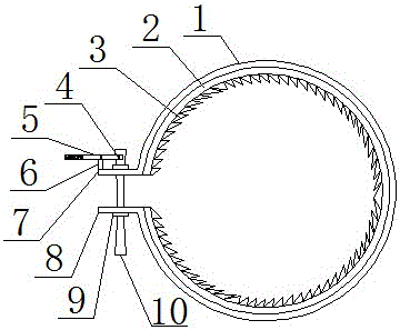
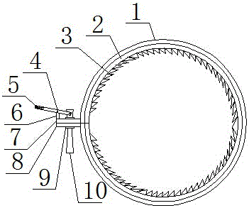
[0019] see Figure 1-3 , a clamping device for concrete-filled steel tube members with special-shaped sections, including 1 helical clamp, 2 belt teeth, 3 teeth, 4 rotating shafts, 5 joysticks, 6 pillars, 7 upper chucks, 8 lower chucks, and 9 locking rings and 10 transmission rods; the clamping device of the special-shaped section concrete-filled steel pipe member is a double-layer structure, and the spiral clamper 1 is the outer structure of the clamping devi...


PUM


Abstract

The invention discloses a clamping device for a steel pipe concrete member with a specially-shaped section. The clamping device comprises a spiral clamp, belt teeth, teeth, a rotating shaft, an operation lever, a supporting column, an upper chuck, a lower chuck, a locking ring and a transmission rod. The clamping device has the beneficial effects that the clamping device is compact in structural connection and easy to use; the clamping device adopts an up-pulling and down-pressing dual operation mode to lock the member clamped by the clamping device, so that looseness of the clamping due to directional operation can be effectively prevented, and the operation is facilitated; the transmission rod which is of a structure with a thin middle part and two thick ends penetrates through the upper and lower chucks so that the transmission rod can be prevented from falling off from the clamping device, and the use stability of the clamping device is improved; the clamping device is of a double-layer structure; the outer layer is the spiral clamp for fixedly clamping the member, and the inner layer is equipped with a plurality of belt teeth, each of which can extend and retract freely, for determining the shape of the section of steel pipe concrete; therefore, seamless and firm clamping for the specially-shaped steel pipe concrete is facilitated; the clamping device is high in stability and suitable for being popularized and used during working.

Description

technical field [0001] The invention relates to a clamping device, in particular to a clamping device for a steel pipe concrete member with a special-shaped section, belonging to the field of construction equipment. Background technique [0002] With the development of society and the prosperity of the construction industry, the concrete-filled steel tube structure is indispensable in construction engineering, but the pouring of the concrete-filled steel tube structure requires an external clamping device to clamp it, which is convenient for the stability of the concrete-filled steel tube pouring. To improve the ornamental value, the concrete-filled steel tube structure will have some special-shaped sections, and the existing clamping device is not suitable for clamping the special-shaped section concrete-filled steel tube, and the clamping is unstable. device. [0003] At present, there are some deficiencies in the clamping device for concrete-filled steel tube members wit...

Claims


Application Information

Patent Timeline
Patent Type & Authority Applications(China)
IPC IPC(8): E04G13/00E04G13/02
CPCE04G13/00E04G13/021E04G13/026
Inventor 董江峰侯敏王清远
Owner SICHUAN UNIV
Why Eureka
Try Eureka