
Apparatus for generating electric power

a technology for electric power generators and electrical equipment, applied in the direction of electric generator control, mechanical equipment, machines/engines, etc., can solve the problems of large equipment as a whole, not quite applicable, etc., and achieve the effect of convenient adjustment, convenient adjustment, and convenient connection structur

Inactive Publication Date: 2013-09-03
LINEAR CIRCUIT
View PDF14 Cites 5 Cited by
  • Summary
  • Abstract
  • Description
  • Claims
  • Application Information

AI Technical Summary

Benefits of technology

The patent is about a device that helps to move a flotation device up and down for use in waves. The device has a vibrating or swinging member that moves within a vertical plane. The device is designed to be simple and easy to assemble. Additionally, the device has a rotating member that can connect to a power generation unit, allowing for a compact and smooth rotation of the flotation device.

Problems solved by technology

However, this system requires large equipment as a whole and is therefore not quite applicable as a facility of low capacitance.

Method used


Image

  • Apparatus for generating electric power
  • Apparatus for generating electric power
  • Apparatus for generating electric power

Examples


Embodiment Construction

[0032]Embodiments of the present invention are described below with reference to the drawings.

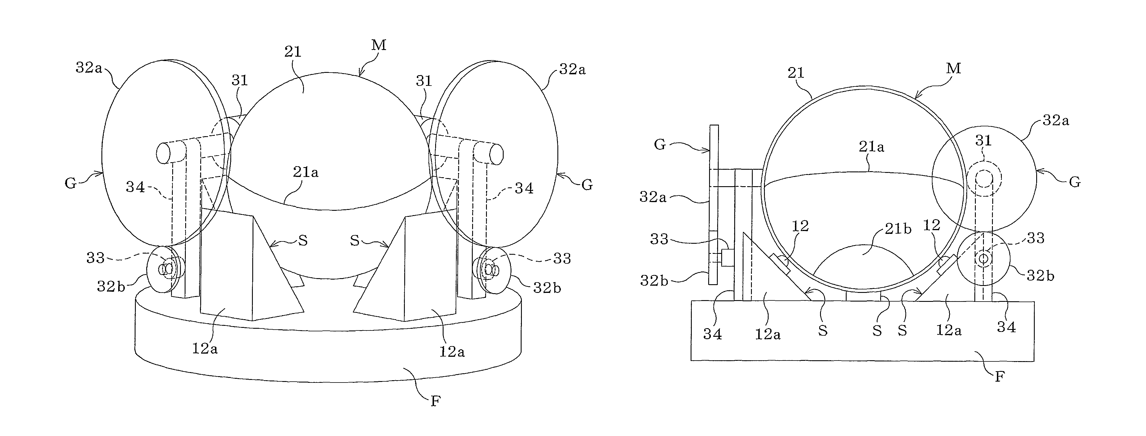
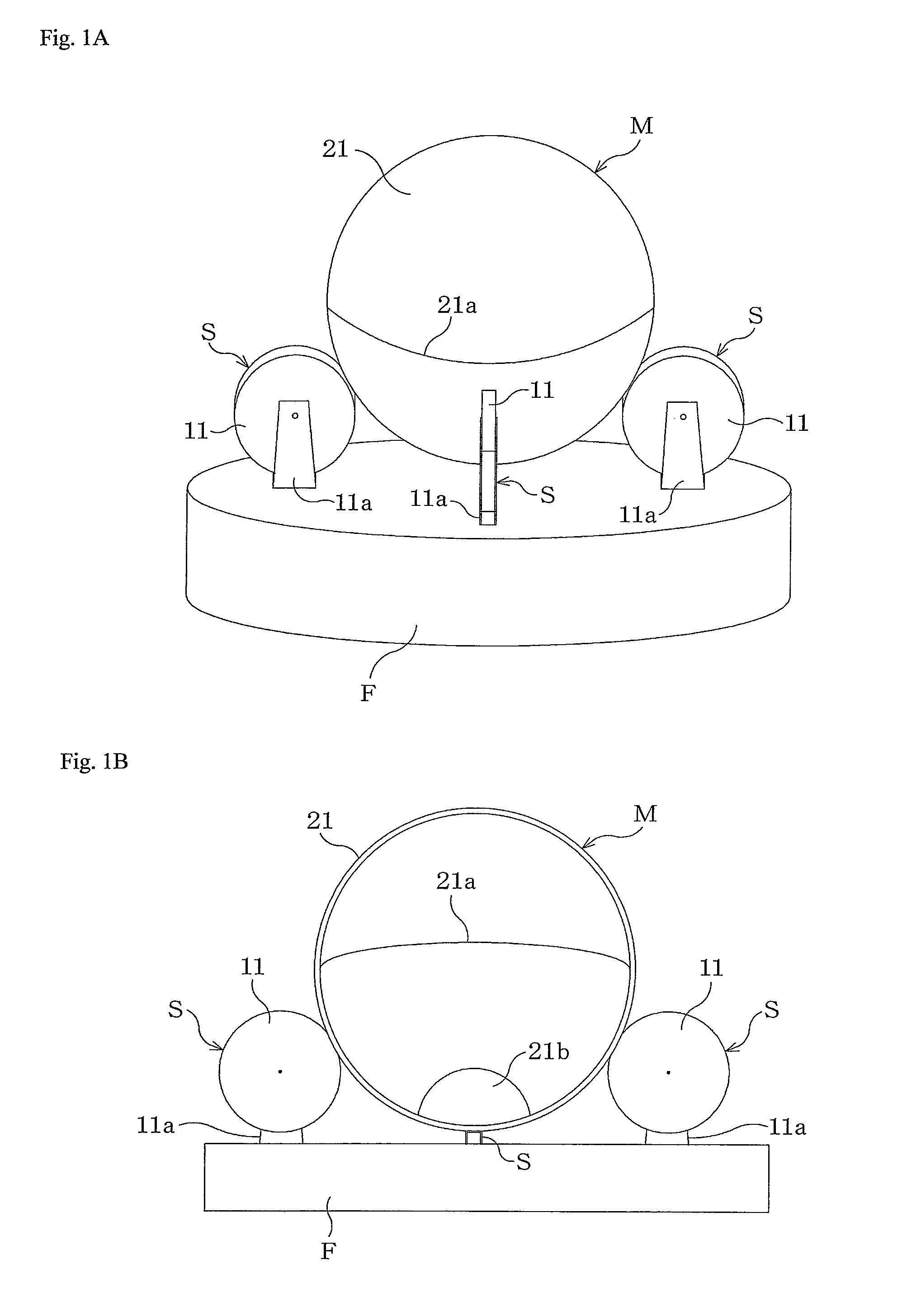
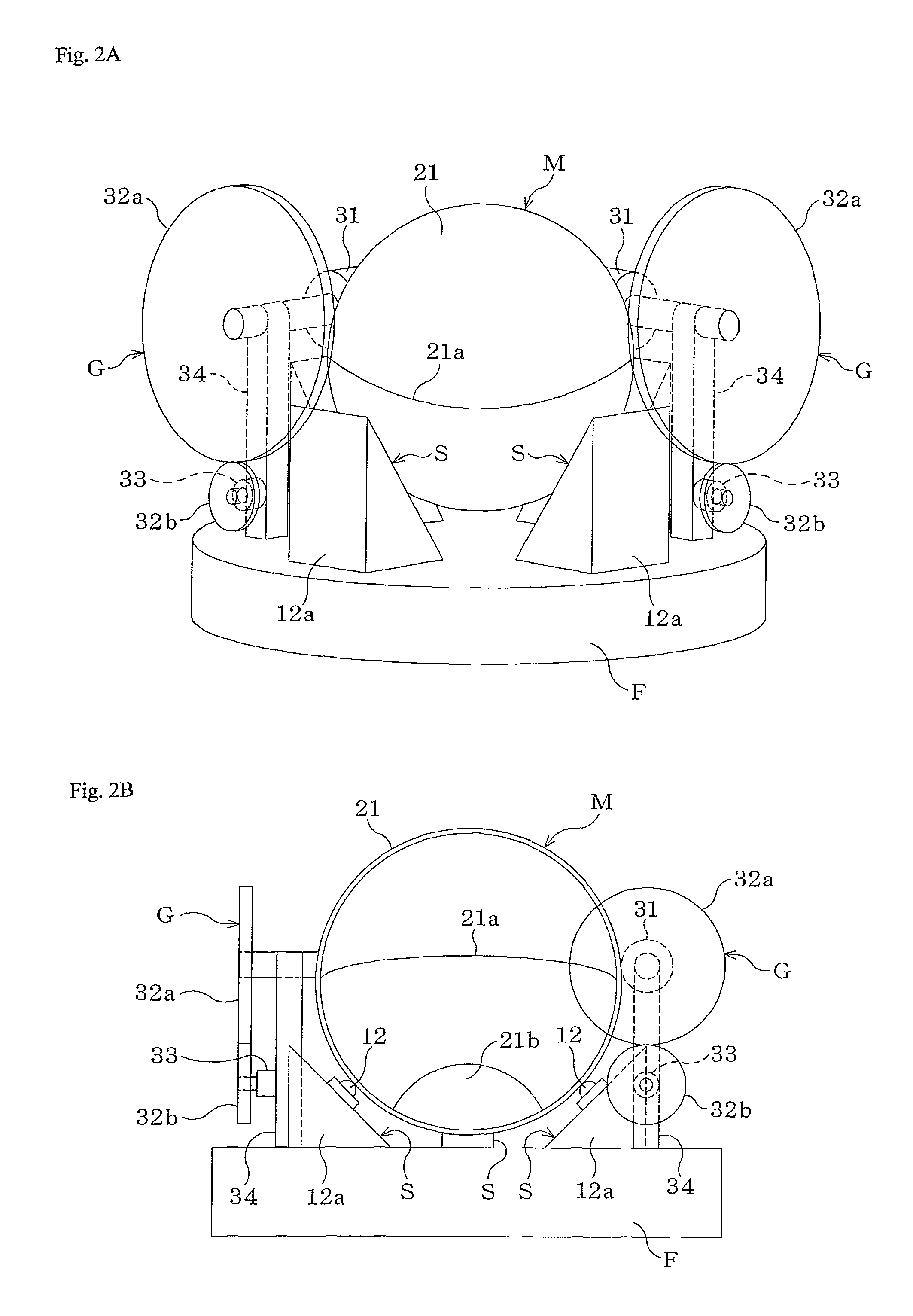
[0033]A power generator includes a float F, supporting members S, S, and a movable member M that is mounted on the float F with the supporting members S, S, . . . being interposed therebetween (FIGS. 1A and 1B). FIG. 1A is a schematic perspective view of an entire structure, and FIG. 1B is a vertical sectional view at the center of the entire structure.

[0034]The float F is formed in the shape of a circular flat plate and can be floated on the surface of the sea. Provided on the float F are the four supporting members S, S, . . . that are arranged to form a cross shape. Each of the supporting members S includes a bracket 11a standing on the float F and a supporting roller 11 rotatably attached to the bracket 11a.

[0035]The movable member M is formed as a hollow spherical body 21. The spherical body 21 can be separated into an upper portion and a lower portion at a central joint portion 21a. ...


PUM


Abstract

A power generator that can be utilized as a small facility of low capacitance. The power generator comprises a float that is placed on a surface of the sea, supporting members mounted on the float, and a movable member supported by the supporting members and can be movable by the swing motion of the float caused by waves.

Description

BACKGROUND OF THE INVENTION[0001]1. Field of the Invention[0002]The present invention relates to a power generator that floats on the surface of the sea or the like to generate electric power using waves.[0003]2. Description of the Related Art[0004]The technology of generating electric power with use of the energy of waves emerging on the surface of the sea is known as so-called wave power generation.[0005]In the wave power generation technology, there is a swinging plate system in which a swinging plate is hung in a water chamber open to the travel direction of waves so as to be swung forward and backward with the use of standing waves emerging in the water chamber.[0006]This system achieves high power generation efficiency because kinetic energy and potential energy of waves can be entirely and efficiently transduced to electric energy (for example, “Wave power generation for practical application”, Tomiji WATABE, POWERSHA Inc., May 25, 2009, pp. 34-57).[0007]The power generation ...

Claims


Application Information

Patent Timeline
Patent Type & Authority Patents(United States)
IPC IPC(8): F03B13/00
CPCF03B13/20Y02E10/38Y02E10/30F05B2250/44
Inventor ONO, HIROAKI
Owner LINEAR CIRCUIT
Learn More