Connecting member

A technology for connecting components and components, which is applied to the parts, connections, and conductive connections of the connection device, which can solve the problems of time-consuming installation of electrical wiring circuits, unfavorable miniaturization of wire electrical wiring, and inability to branch, etc., to achieve shortening Operation time, simple structure, and improved reliability

Inactive Publication Date: 2009-06-10
FURUKAWA ELECTRIC CO LTD +1
View PDF1 Cites 6 Cited by
  • Summary
  • Abstract
  • Description
  • Claims
  • Application Information

AI Technical Summary

Problems solved by technology

However, since the number of parts such as connectors and mating-side universal connectors, bus bars, and connection terminals is large, it is actually time-consuming to install the wiring circuit
[0007] In particular, in the wire harness using the connection connector disclosed in Patent Document 1, the connection connector is relatively large, so branching cannot be performed at the branching point, and the electric wire must be extended to a place where the space for accommodating the connection connector is available. It is not conducive to the miniaturization of wire electrical wiring

Method used


Image

  • Connecting member
  • Connecting member
  • Connecting member

Examples


Embodiment 1

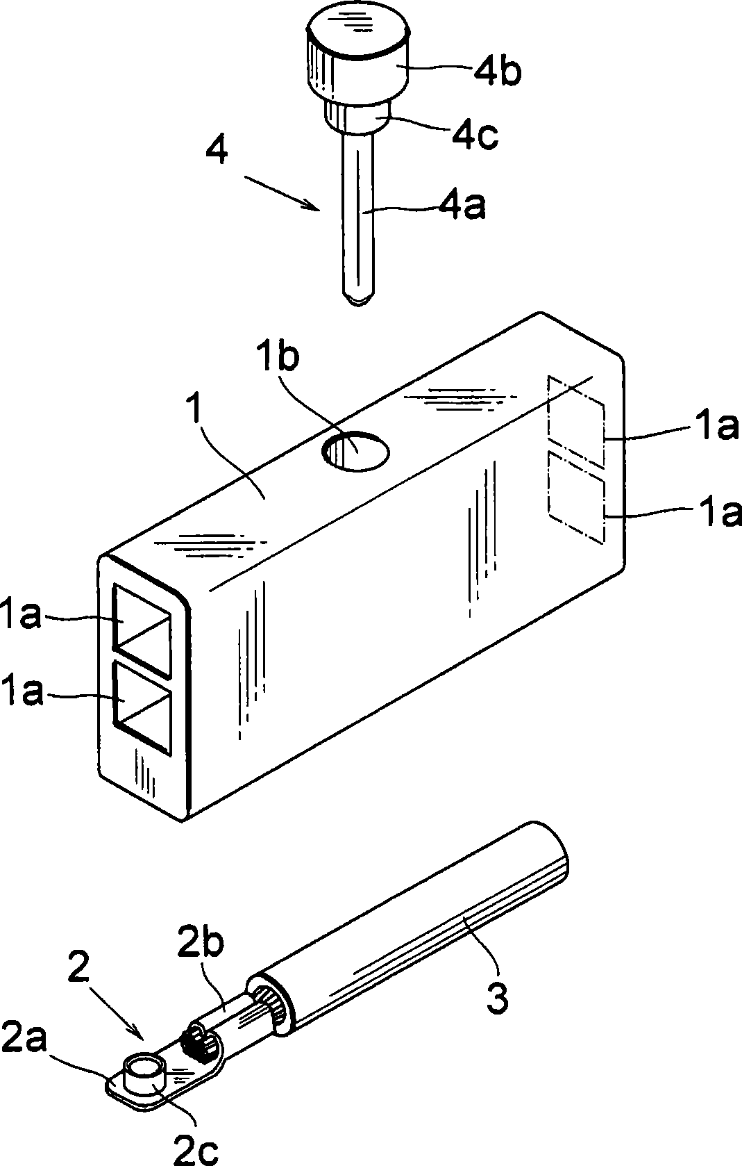
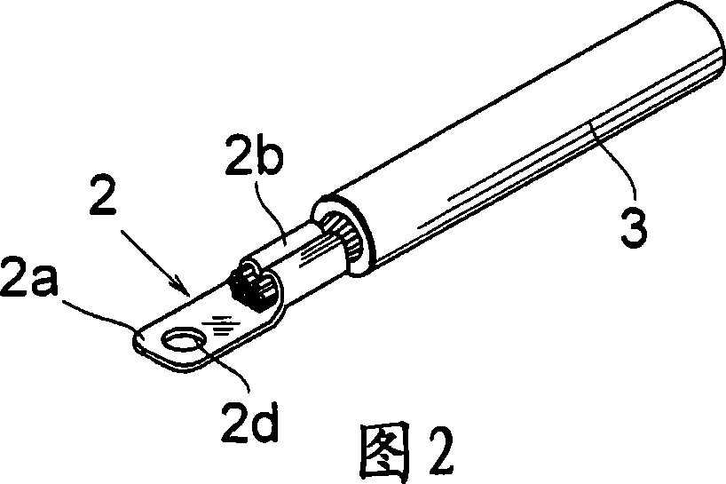
[0030] In Example 1, such as figure 1 As shown in the exploded perspective view of , it is composed of the following components: a holding body 1 made of synthetic resin material having an electric wire terminal insertion hole 1a and a pin terminal insertion hole 1b; A plurality of electric wire terminals 2 of the crimping portion 2b; and a piercing pin 4 composed of a pin terminal 4a, a grip portion 4b, and an intermediate portion 4c.

[0031] A plurality of electric wire terminal insertion holes 1a are formed in the holding body 1 from the left and right sides toward the center, for example, by making the entrance part a square hole, so that the receiving connection end 2a can be inserted to a predetermined position. In addition, the pin terminal insertion hole 1b is formed in the central direction from the upper side of the holder 1, and is formed so as to be perpendicular to the position where the wire terminal insertion hole 1a receives the connection end 2a.

[0032] As...

Embodiment 2

[0053] Figure 7 A perspective view of an assembly of the holder 1, the electric wire terminal 2, and the pin 4 of the waterproof type Example 2 is shown. FIG. 8 shows a perspective view of an assembled state, and FIG. 9 shows a cross-sectional view thereof.

[0054] A cylindrical waterproof seal 5 made of synthetic rubber is inserted into the electric wire 3 on the electric wire terminal 2 side, and is fixed by a seal crimping portion 2 f extending from the electric wire terminal 2 . In addition, the cross section of the entrance of the electric wire terminal insertion hole 1 a of the holding body 1 is circular, and is sealed by a waterproof packing 5 .

[0055] A cylindrical waterproof packing 6 is also inserted in the intermediate portion 4c of the pin 4, and the waterproof packing 6 is attached to the circular entrance of the pin terminal insertion hole 1b.

[0056] In this embodiment 2, waterproof seals 5, 6 can be used to prevent water from infiltrating into the inside ...


PUM


Abstract

Provided is a connecting member by which an electric wire can be branched easily with high reliability. Receptacle connecting ends (2a) of a plurality of wire terminals (2) having wires (3) are inserted into a wire terminal inserting hole (1a) of a holder (1), then, a pin terminal (4a) is inserted into a pin terminal inserting hole (1b) of the pin terminal (4a). The pin terminal (4a) is inserted through a tubular contact (2c) of the receptacle connecting ends (2a) arranged in the pin terminal inserting hole (1b), and electricity is carried between the wire terminals (2) through the pin terminals (4a).

Description

technical field [0001] The present invention relates to connecting parts for wiring circuits of automobiles, for example. Background technique [0002] In the electrical wiring circuit of automobiles, it is often necessary to branch out multiple branch lines from the main line. Therefore, in the past, the following two methods were used: peeling off part of the covering layer of the trunk line, crimping the branch line on the exposed conductor to realize the splicing connection method of the branch; and configuring the circuit branch connector at the end of the trunk line, For example, the connecting member method described in Patent Document 1 is branched using trunk lines, branch lines, general-purpose connectors, and crimp terminals. [0003] Patent Document 1: (Japanese) Unexamined Patent Publication No. 2005-71614 [0004] Problems Solved by the Invention [0005] In the former splicing connection method, it is necessary to perform crimping processing for every 1 to ...

Claims


Application Information

Patent Timeline
Patent Type & Authority Applications(China)
IPC IPC(8): H01R31/08H01R11/12H01R13/52
CPCH01R13/4361H01R11/12H01R31/08
Inventor 村野广昭松本智和田中义和广濑铁
Owner FURUKAWA ELECTRIC CO LTD
Why Eureka
Try Eureka