Air suction valve and compressor

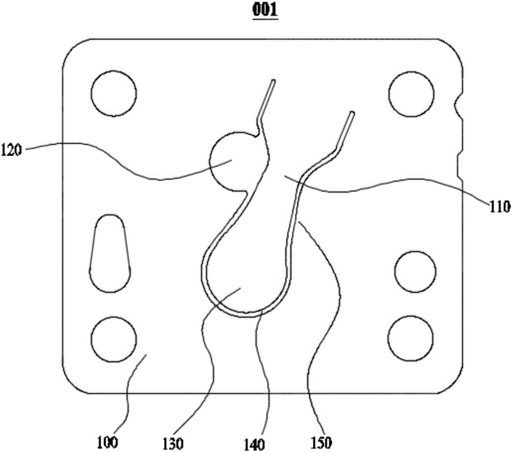
A suction valve and reed technology, applied in the field of refrigeration compressor accessories, can solve the problems of reducing the suction efficiency of the suction valve 001, reducing the structural strength of the reed 110, and the unbalanced force of the reed 110, etc., to achieve Effects of reducing force deformation, improving ventilation efficiency, and increasing gap length

Active Publication Date: 2017-01-04
黄石东贝压缩机有限公司
View PDF5 Cites 1 Cited by
  • Summary
  • Abstract
  • Description
  • Claims
  • Application Information

AI Technical Summary

Problems solved by technology

This is because under the same cross-sectional area, the edge length of the reed 110 with a circular (or oval) reed end 130 is relatively small, so that the length of the gap 140 between the reed 110 and the valve plate 100 is relatively small, Thereby reducing the suction efficiency of the suction valve plate 001; at the same time, both sides of the reed 110 of the suction valve plate 001 have contracted parts 150 contracted inwardly, and the contracted parts 150 on both sides of the reed end 130 and the reed 110 The convex-concave combination makes the stress concentrate on the end 130 of the reed, which reduces the structural strength of the reed 110, and the vent hole 120 provided on the side of the reed 110 will also make one side of the reed 110 bear more force than the other side, so that the reed 110 Unbalanced force produces a large torque, which reduces its service life

Method used


Image

  • Air suction valve and compressor
  • Air suction valve and compressor
  • Air suction valve and compressor

Examples


Embodiment 1

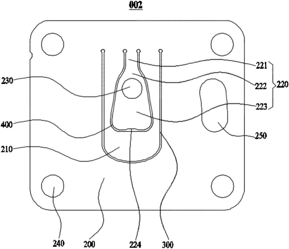
[0032] Such as figure 2 As shown, the present embodiment provides a suction valve plate 002, which includes a valve plate 200, on which a first reed 210 is provided, and a U-shaped first reed 210 is formed between the first reed 210 and the valve plate 200. A ventilation gap 300, the first reed 210 is provided with a second reed 220, a second ventilation gap 400 is formed between the second reed 220 and the first reed 210, and a ventilation hole 230 is opened on the second reed 220 ; The valve plate 200 is provided with a plurality of fixing holes 240 for fixing the valve plate 200 . The length of the first reed 210 is 2-2.2 times of its width, and a positioning hole 250 is opened on the valve plate 200 . Specifically, both the first reed 210 and the second reed 220 are made by stamping, the four corners of the valve plate 200 are respectively provided with a fixing hole 240, and the positioning hole 250 is a bar-shaped hole and is located on one side of the first ventilatio...

Embodiment 2

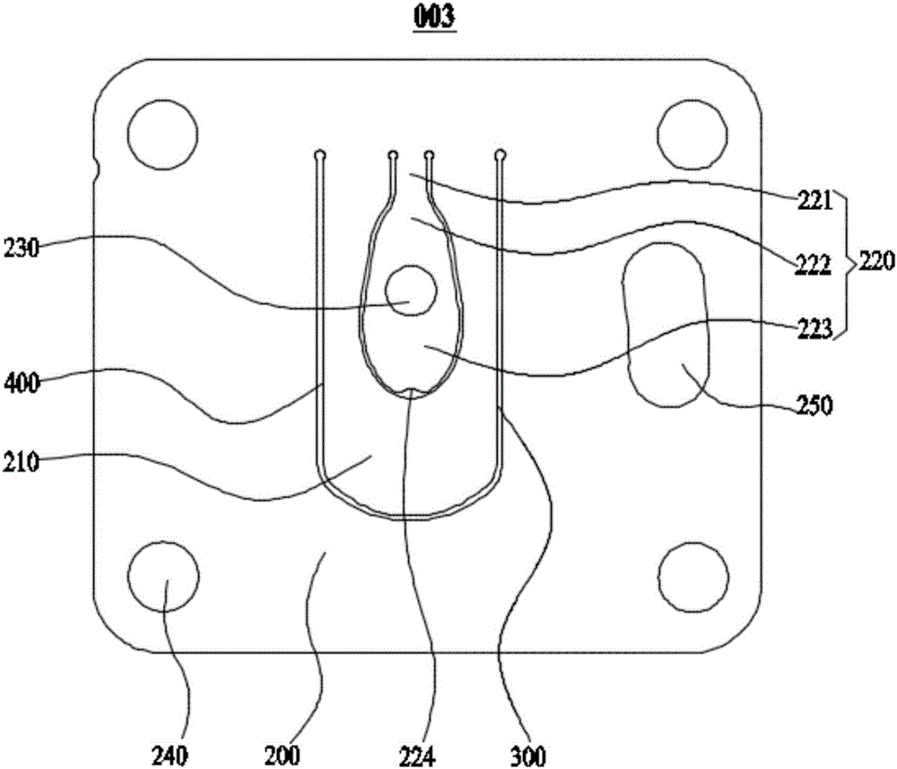
[0042] Such as image 3 As shown, this embodiment provides a suction valve plate 003, which includes a valve plate 200, on which a first reed 210 is provided, and there is a U-shaped first reed between the first reed 210 and the valve plate 200. The ventilation gap 300, the first reed 210 is provided with the second reed 220, the second reed 220 and the first reed 210 have a second ventilation gap 400, and the second reed 220 is provided with a ventilation hole 230; The valve plate 200 is provided with four fixing holes 240 for fixing the valve plate 200 , and the valve plate 200 is provided with a positioning hole 250 . The length of the first reed 210 is 2.2 times its width.

[0043] The second reed 220 includes a fixed part 221, a transition part 222 and a terminal part 223 arranged in sequence, the fixed part 221 is connected with the valve plate 200, and the end edge of the terminal part 223 away from the transition part 222 is provided with a recessed part 224, and the ...

Embodiment 3

[0047] Such as Figure 4 As shown, this embodiment provides a compressor 004 for refrigeration, which is installed with the suction valve plate 002 provided in the first embodiment above.

[0048] The compressor 004 for refrigeration installed with the above-mentioned suction valve plate 002 has high suction efficiency, long service life, low failure rate, and can better meet the use requirements.


PUM


Abstract

The invention relates to an air suction valve and a compressor, belonging to the field of refrigerating compressor accessories. The air suction valve comprises a valve plate, wherein a first reed is arranged on the valve plate, a U-shaped first ventilation clearance is formed between the first reed and the valve plate, a second reed is arranged on the first reed, a second ventilation clearance is formed between the second reed and the first reed, and a ventilation hole is formed in the second reed. The air suction valve has the advantages that the structure strength is large, the air suction efficiency is high, and the service life is long. The invention further provides a compressor using the air suction valve, and the compressor is high in air suction efficiency and low in fault rate.

Description

technical field [0001] The invention relates to the field of refrigeration compressor accessories, in particular to a suction valve plate and a compressor. Background technique [0002] The suction valve is an important part of the compressor. It is mainly used to control the gas flow into and out of the compressor. The performance of the suction valve directly affects the suction efficiency of the compressor. The suction valve plate is generally composed of a valve plate, a reed on the valve plate and a vent hole. During the suction and exhaust process of the compressor, a pressure difference is generated on both sides of the suction valve plate, and the compressed gas passes through the vent hole. Pass the valve plate and push the reed to produce deformation, so that more compressed gas will pass through the suction valve plate from the gap between the reed and the valve plate, so the size of the gap between the reed and the valve plate affects the suction of the compresso...

Claims


Application Information

Patent Timeline
Patent Type & Authority Applications(China)
IPC IPC(8): F04B39/10
CPCF04B39/1033F04B39/1086
Inventor 曹烜炜窦作为万朋鲁硕程恺
Owner 黄石东贝压缩机有限公司
Why Eureka
Try Eureka