Rack connection part installation structure

A technology for connecting parts and mounting structures, applied in the direction of fixing devices, storage devices, mechanical equipment, etc., can solve the problem of low compressive stress intensity and achieve the effect of reduced buckling strength and high compressive strength

Active Publication Date: 2019-07-23
DAIFUKU CO LTD
View PDF2 Cites 0 Cited by
  • Summary
  • Abstract
  • Description
  • Claims
  • Application Information

AI Technical Summary

Problems solved by technology

In this structure, although it is not necessary to lengthen the lengths of the respective mounting plate portions of the horizontal connecting member and the braces as described above, when the horizontal connecting member receives compressive stress, the mounting plate portion becomes one-way from the axial center of the pipe member. Due to the eccentric state of side shifting, the strength (endurance) against compressive stress becomes lower, and the problem of strength is not solved as a result.

Method used


Image

  • Rack connection part installation structure
  • Rack connection part installation structure
  • Rack connection part installation structure

Examples


Embodiment Construction

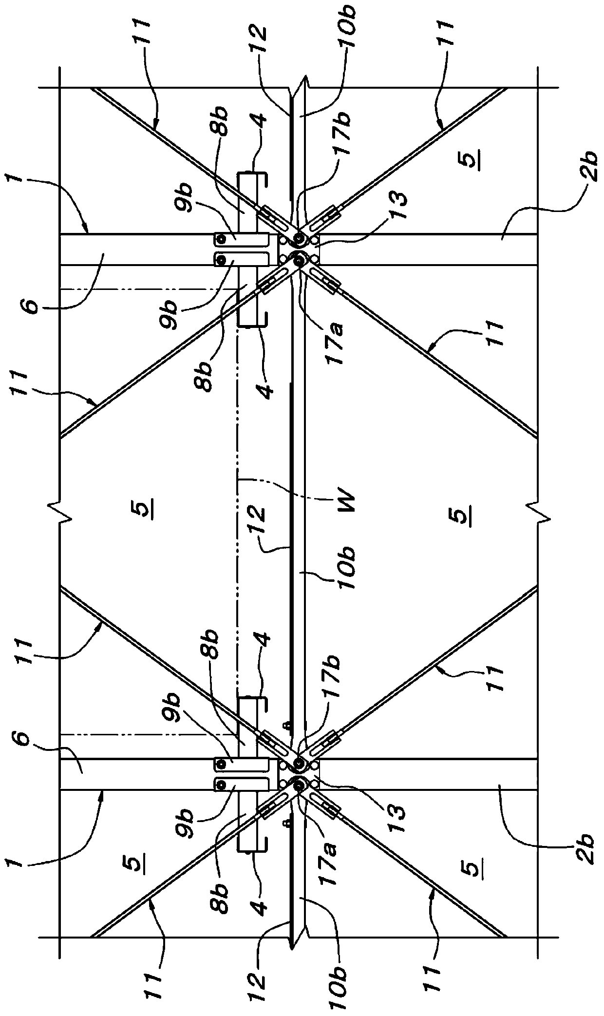
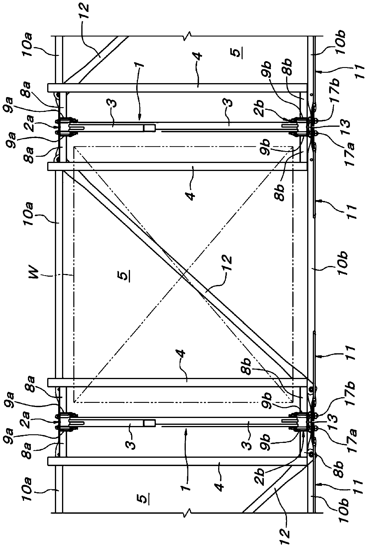
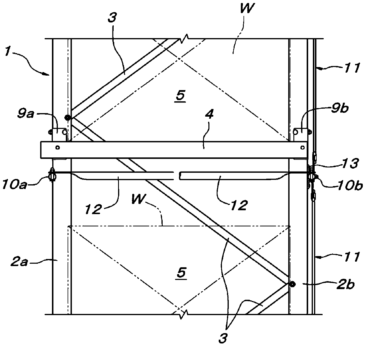
[0052] exist Figure 1 ~ Figure 3 Among them, 1 is a vertical frame structure for partition, which is erected at predetermined intervals in the lateral width direction of the rack. Each partition vertical frame structure 1 is a lattice structure constituted by a pair of front and rear pillars 2a, 2b and a lattice portion 3 that integrally connects the pair of front and rear pillars 2a, 2b. Between the vertical frame structures 1 for separation adjacent to each other in the width direction of the rack, a multi-stage article support section 5 up and down is formed. A pair of left and right article support members 4 for side support. The front and rear pairs of pillars 2a and 2b are formed in a front-rear symmetrical orientation with the front panel 6 and the left and right side panels 7 made of steel. The front and rear ends of each article supporting member 4 are attached to a pair of front and rear columns 2a, 2b via arm portions 8a, 8b parallel to the frame width direction ...


PUM


Abstract

According to the present invention, an installation structure which is arranged at and is connected with the transverse direction of a rack and is vertical with the horizontal connection parts and the pull strips of the frame structure bodies, is improved. A connection part installation structure of the rack is formed in the following manners that a formation installation plate part 22 which is formed by pressing and deforming the end part of a pipe part 24 of a horizontal connection part 10b is formed at the central position of the pipe part 24 when the pipe part is observed axially, and the length 26L of a flat surface part 26 which is at the outer side surface of the formation installation plate part 22 and is overlapped with an installation plate part 23 of the pull strip 11 is longer than the length 25L of the flat surface part 25 which is at the inner side surface of the formation installation plate part 22 and is overlapped with a connection part installation plate 13, and the peripheral surface of the pipe part protruded from the flat surface parts 25, 26 of the formation installation plate part 22 in the horizontal connection parts 10b is not overlapped with the installation plate parts 23 of the connection part installation plate 13 and the pull strip 11.

Description

technical field [0001] The present invention relates to an installation structure of connecting members such as horizontal connecting members and braces connecting vertical frame structures arranged in the lateral width direction of a rack. Background technique [0002] As shown in Patent Document 1 and Patent Document 2, in a general rack with a frame structure, a vertical frame structure such as a lattice structure arranged on both sides of an article supporting space is passed through horizontal connecting members (horizontal beam members), braces, etc. It is constructed by connecting and integrating various connecting members such as various connecting members, and attaching an article supporting member for supporting articles to a vertical frame structure. In the vertical frame structure, generally, the front and rear pairs of pillars are connected and integrated by lattice members, etc., and generally, the horizontal lattice members installed on the pillars or installe...

Claims


Application Information

Patent Timeline
Patent Type & Authority Patents(China)
IPC IPC(8): B65G1/14F16B1/00
CPCB65G1/14F16B1/00
Inventor 中村良彦长谷川丰杉村泰司堂场直树上田信
Owner DAIFUKU CO LTD
Why Eureka
Try Eureka