Supercharge Your Innovation With Domain-Expert AI Agents!

Locking mechanism and method for an electro-pneumatic controller

一种气动控制器、锁定机构的技术,应用在非电动变量控制、电动方式的流体压力控制、发动机元件等方向,能够解决损坏、安装麻烦、增加无效锁定的概率等问题

Inactive Publication Date: 2017-01-04
TESCOM CORP
View PDF0 Cites 0 Cited by
  • Summary
  • Abstract
  • Description
  • Claims
  • Application Information

AI Technical Summary

Problems solved by technology

[0005] However, the locking assembly 16 is bulky and cumbersome to install due to its three-part (e.g., main body 20, guide pin 22, and screw 24) configuration, e.g. The notch of 16 is aligned with 28
Furthermore, since there are three parts to the locking assembly 16, there is an increased risk of errors in installing each of these parts, which increases the chance of an invalid lock and ultimately damage and / or injury

Method used


Image

  • Locking mechanism and method for an electro-pneumatic controller
  • Locking mechanism and method for an electro-pneumatic controller
  • Locking mechanism and method for an electro-pneumatic controller

Examples


Embodiment Construction

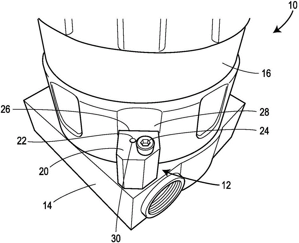
[0025] In summary, a one-piece or one-piece locking mechanism for a cover of an electro-pneumatic controller for use with a regulator is disclosed. The electro-pneumatic controller includes a base having a body, a top surface, and an aperture formed in the body. The one-piece locking mechanism is disposed within the bore of the base and includes a top surface that is flush with the top surface of the base. A cover is coupled to the base and includes an open end having a rim. The edge contacts a portion of the top surface of the locking mechanism and the top surface of the base. With a single tool such as an Allen wrench (Allen wrench), the locking mechanism is turned upwards in a counterclockwise direction to lock the cover to the base.

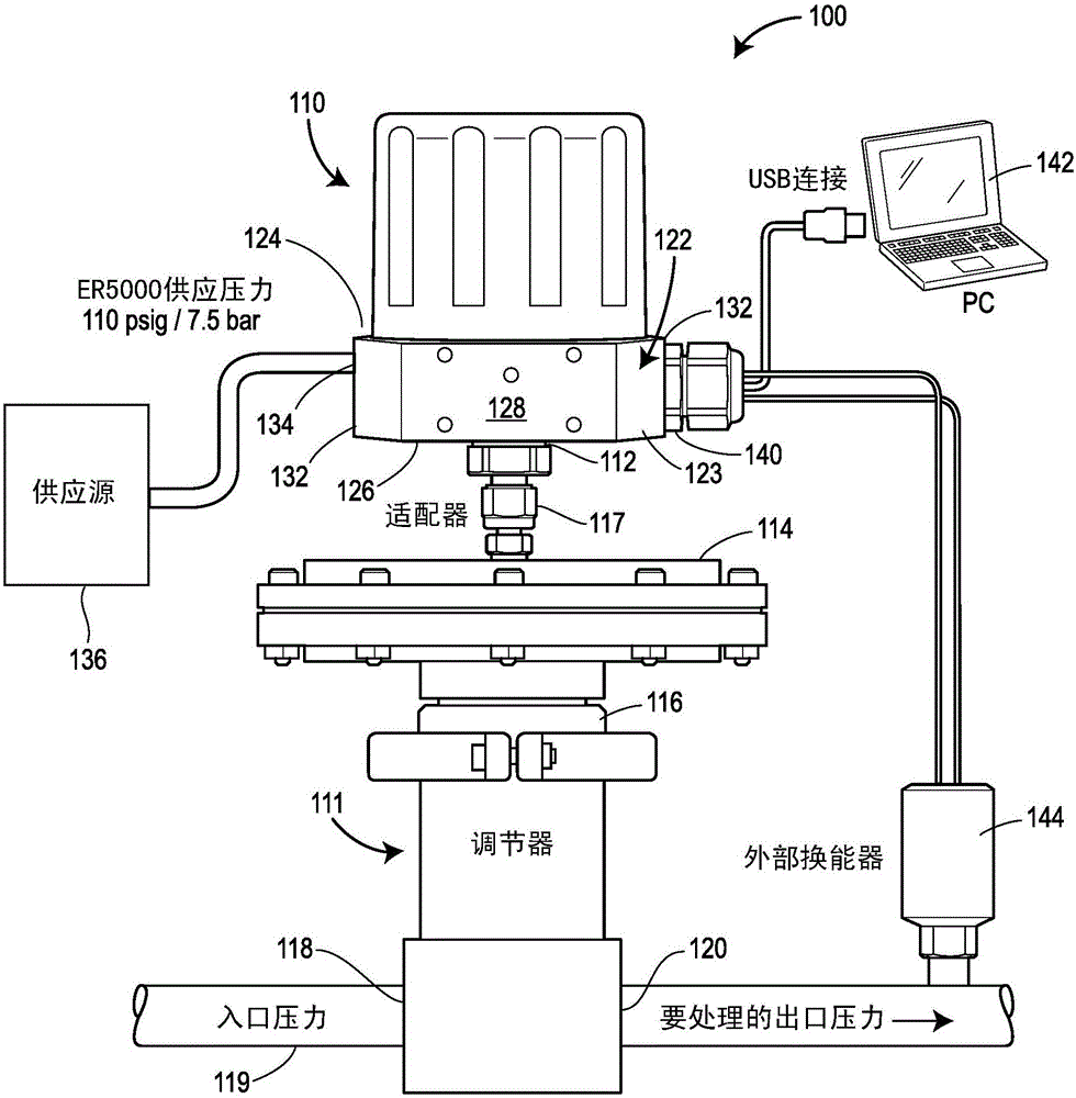
[0026] see now figure 2 , the process control system 100 includes an electro-pneumatic controller 110 operatively coupled to a regulator 111 . In particular, outlet port 112 of electro-pneumatic controller 110 is operatively coupled to t...


PUM


Abstract

An electro-pneumatic controller for use with a regulator. The electro-pneumatic controller includes a base having a body, a top surface, and a bore formed within the body. A locking mechanism is disposed within the bore of the body of the base, the locking mechanism having a top surface flush with the top surface of the base. A cover is coupled to the base and includes an open end with a rim, the rim contacting the top surface of the base and a portion of the top surface of the locking mechanism. The locking mechanism is rotated via a tool in a counter-clockwise direction after the cover contacts a portion of the top surface of the locking mechanism to lock the cover to the base.

Description

technical field [0001] In general, the present invention relates to controls for process control valves and, more particularly, to cover locks for electro-pneumatic controls. Background technique [0002] Typically, an electro-pneumatic controller (also referred to as an electro-pneumatic regulator) is used to control the pressure of a control fluid used to position a pneumatic control device (eg, a regulator). For example, an electro-pneumatic controller may be used to control the pressure of a control fluid to a pneumatic actuator of a process control valve or regulator to position the process control valve or regulator. The electro-pneumatic controller may include one or more channels for receiving control fluid, and one or more solenoid valves may control the flow of the control fluid through the channels. The one or more solenoid valves may communicate with a microprocessor, which may communicate with one or more sensors external to the electro-pneumatic controller to ...

Claims


Application Information

Patent Timeline
Patent Type & Authority Applications(China)
IPC IPC(8): F16K27/12F16K35/06F16K31/00G05D16/00
CPCF16K27/12F16K31/00F16K35/06G05D16/00F16K35/10F16K31/04Y10T137/7256Y10T137/7761F16B5/025F16B35/005G05D16/20
Inventor J·T·R·雷诺莱特E·J·伯吉特
Owner TESCOM CORP
Features
  • R&D
  • Intellectual Property
  • Life Sciences
  • Materials
  • Tech Scout
  • Unparalleled Data Quality
  • Higher Quality Content
  • 60% Fewer Hallucinations
Learn More