Method for simulating three-dimensional electric field on valve side of converter transformer by considering nonlinearity and anisotropy

A converter transformer, anisotropic technology, applied in the field of three-dimensional electric field simulation on the valve side of the converter transformer, can solve the problem of less research on three-dimensional electric field distribution

Inactive Publication Date: 2017-01-04
CHANGSHA UNIVERSITY OF SCIENCE AND TECHNOLOGY
View PDF4 Cites 20 Cited by
  • Summary
  • Abstract
  • Description
  • Claims
  • Application Information

AI Technical Summary

Problems solved by technology

[0005] The research on the DC electric field at the valve side of the converter transformer in the above literatures mainly focuses on the distribution of the two-dimensional electric field, and less research on the distribution of the three-dimensional electric field. There is no literature on the analysis and calculation of the three-dimensional electric field considering nonlinearity and anisotropy. As a spatial entity, the converter transformer can only accurately analyze the distribution of its spatial electric field through a three-dimensional model, so it is worth further research on the electric field distribution of the converter transformer

Method used


Image

  • Method for simulating three-dimensional electric field on valve side of converter transformer by considering nonlinearity and anisotropy
  • Method for simulating three-dimensional electric field on valve side of converter transformer by considering nonlinearity and anisotropy
  • Method for simulating three-dimensional electric field on valve side of converter transformer by considering nonlinearity and anisotropy

Examples


Embodiment Construction

[0017] The present invention includes the following steps:

[0018] 1. Analysis of electric field under the action of DC voltage

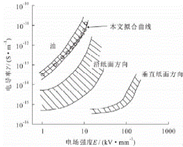
[0019] Due to the working conditions, the converter transformer not only bears the action of AC power frequency voltage, but also bears the action of DC voltage. Under the action of DC voltage, the electric field distribution of the oil-paper composite insulating structure mainly depends on the resistivity of the insulating material, showing a resistive distribution. Therefore, the electric fields under the action of AC and DC voltages are completely different and require different solutions.

[0020] Under the action of DC voltage, the electric field distribution is not only related to the insulating structure, but also to the resistivity of the insulating medium. The internal insulating medium of the converter transformer mainly includes transformer oil, oil-impregnated paper and cardboard. The resistivity of these mediums will be affected by m...


PUM


Abstract

The invention belongs to the field of power system simulation and particularly relates to a method for simulating a three-dimensional electric field on a valve side of a converter transformer. For an existing situation that the researches on the electric field of the converter transformer most focus on two-dimensional electric field modeling analysis and rarely focus on three-dimensional modeling analysis, the invention takes the building of a three-dimensional model of major insulation of the converter transformer as a core and proposes a method for simulating a direct-current electric field of a valve side winding of the converter transformer by considering the nonlinearity and anisotropy of a material. The method comprises the steps of firstly, building the three-dimensional model of the end part of the winding of the converter transformer by utilizing finite element analysis software ANSYS, and performing grid division on the three-dimensional model; secondly, writing a nonlinear anisotropic direct-current electric field computing program by utilizing a secondary development APDL module of ANSYS; and finally, setting a boundary condition, initial resistivity and a loading test voltage, and computing the three-dimensional electric field. According to the method for simulating the three-dimensional electric field on the valve side of the converter transformer by considering the nonlinearity and anisotropy, provided by the invention, a method is provided for improving the precision of simulating the electric field of the converter transformer.

Description

technical field [0001] The invention belongs to the field of power system simulation, in particular to a method for simulating a three-dimensional electric field at the valve side of a converter transformer. Background technique [0002] At present, a number of large-scale DC transmission projects have been built in my country. With the commissioning of these DC transmission projects, the stable operation of DC transmission is becoming increasingly important. The main longitudinal insulation design of power transformers is the calculation design of large-scale transformers, especially ultra-high voltage power transformers. It is not only of great significance to the limit capacity and operational reliability of power transformers, but also has an extremely important impact on the economic indicators of transformers. [0003] At present, the oil and paper composite insulation structure is still generally used inside the large converter transformer. Under normal operation, the...

Claims


Application Information

Patent Timeline
Patent Type & Authority Applications(China)
IPC IPC(8): G06F17/50
Inventor 马瑞曾凯
Owner CHANGSHA UNIVERSITY OF SCIENCE AND TECHNOLOGY
Why Eureka
Try Eureka