
An Image Reconstruction Method for Electric Capacitance Tomography Based on Rof Model

A technology of electrical capacitance tomography and image reconstruction, which is applied in image generation, image data processing, 2D image generation, etc.

Active Publication Date: 2019-01-25
SHENZHEN GRADUATE SCHOOL TSINGHUA UNIV
View PDF9 Cites 0 Cited by
  • Summary
  • Abstract
  • Description
  • Claims
  • Application Information

AI Technical Summary

Problems solved by technology

Therefore, the ECT image reconstruction method based on the concept of "compressed sensing" and the ROF model will be a challenging problem

Method used


Image

  • An Image Reconstruction Method for Electric Capacitance Tomography Based on Rof Model
  • An Image Reconstruction Method for Electric Capacitance Tomography Based on Rof Model
  • An Image Reconstruction Method for Electric Capacitance Tomography Based on Rof Model

Examples


Embodiment Construction

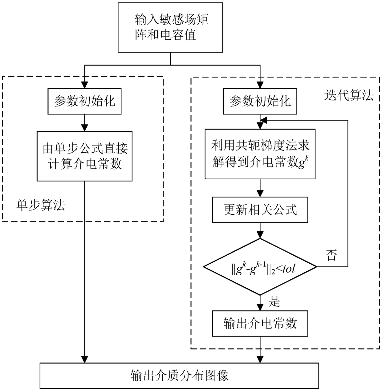
[0094] Such as figure 1 Shown is a flow chart of the present invention, and the present invention comprises the following steps:

[0095] S1, input sensitive field matrix and capacitance value;

[0096] S2, using a single-step algorithm or an iterative algorithm for calculation;

[0097] S3. Outputting the medium distribution image.

[0098] The input sensitive field matrix and capacitance value are to establish the linearization model of ECT:

[0099] λ=Sg (1)

[0100] In the formula: λ is the normalized capacitance vector of m×1, S is the normalized sensitive field matrix of m×n, and g is the normalized permittivity vector of n×1;

[0101] The single-step algorithm described in step S2 comprises the following steps:

[0102] S21, parameter initialization;

[0103] S22. Directly calculate the dielectric constant by a single-step formula.

[0104] The iterative algorithm described in step S2 comprises the following steps:

[0105] S31, parameter initialization;

[010...


PUM


Abstract

The invention discloses an image reestablishment method for electrical capacitance tomography based on an ROF (Rudin-Osher-Fatemi) model. The Rudin-Osher-Fatemi model is applied to image reestablishment for the electrical capacitance tomography. Through adoption of a single-step or iterative reestablishment algorithm, the defects of an existing algorithm in flow pattern edge preservation and anti-noise aspects are overcome, and the quality of a reestablished image is improved.

Description

technical field [0001] The invention relates to the technical field of electrical capacitance tomography, in particular to an image reconstruction method of electrical capacitance tomography based on an ROF model. Background technique [0002] In the field of multiphase flow detection, electrical capacitance tomography (ECT) is a new monitoring technology that can visualize the distribution of media in pipeline space. The basic principle of ECT is to place an array of capacitive sensors around industrial pipelines to measure the capacitance between two electrodes of the capacitive sensor. According to the capacitance value and a specific algorithm, the ECT system can reconstruct the medium distribution in the sensor monitoring area, so as to determine the flow pattern characteristics inside the pipeline. ECT technology has the advantages of no radiation, non-invasive, low cost and high speed, so it is widely used in petroleum, chemical, electric power and metallurgy and oth...

Claims


Application Information

Patent Timeline
Patent Type & Authority Patents(China)
IPC IPC(8): G06T11/00
CPCG06T11/003G06T2211/424
Inventor 陈教选刘银艳李轶
Owner SHENZHEN GRADUATE SCHOOL TSINGHUA UNIV
Learn More