
Camera reading type lottery terminal

A technology for terminals and lottery tickets, applied in lottery equipment, instruments, time registers, etc., to reduce costs and failure rates, improve lottery identification efficiency, and solve parts wear problems

Inactive Publication Date: 2017-01-04
北京亚博高腾科技有限公司
View PDF8 Cites 0 Cited by
  • Summary
  • Abstract
  • Description
  • Claims
  • Application Information

AI Technical Summary

Problems solved by technology

It fundamentally solves the problem of component wear, and at the same time greatly improves the reading speed and work efficiency of lottery tickets

Method used


Image

  • Camera reading type lottery terminal
  • Camera reading type lottery terminal
  • Camera reading type lottery terminal

Examples


Embodiment Construction

[0036] The present invention will be further described in detail below in conjunction with the accompanying drawings and specific embodiments.

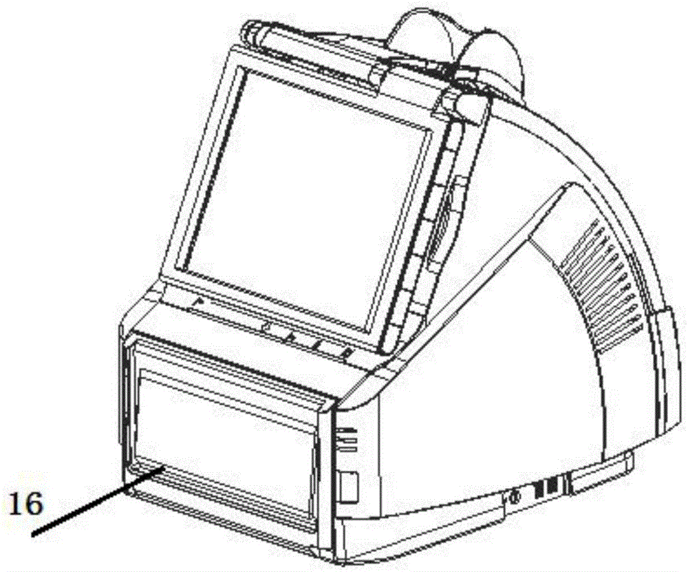
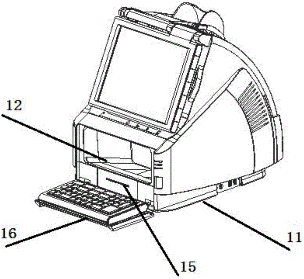
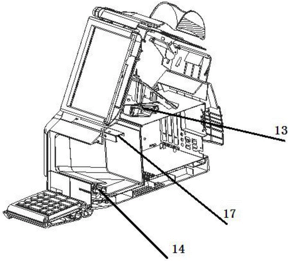
[0037] as attached Figure 1-4 As shown, the camera-reading type lottery terminal of the present invention includes a housing 11, the housing 11 is provided with a reading chamber 12, and the reading chamber 12 is provided with a supplementary light device. The upper part is provided with a camera-reading module 13 for photographing and decoding ticket image information, and the camera-reading module 13 is electrically connected to the reading chamber body 12, and the housing 11 is also provided with a mark printer 14, and the mark print The 14th machine is electrically connected with the reading bin body 12 through a transmission mechanism (not shown in the figure).

[0038] In this embodiment, the camera-reading module 13 is connected to a supplementary light device, further, the supplementary light device is a supplementary light ...


PUM


Abstract

The invention relates to a camera reading type lottery terminal. The lottery terminal comprises a casing, wherein a reading bin is formed in the casing, a light filling device is arranged in the reading bin, a camera reading module for shooting and decoding lottery image information is arranged at the upper part of the reading bin and electrically connected with the reading bin, the casing is further provided with a marking printer, and the marking printer is electrically connected with the reading bin through a transmission mechanism. The lottery terminal has the advantages as follows: a new reading mode is realized, and the abrasion process of the transmission mechanism and a reading head does not exist, so that the cost and the fault rate of terminal equipment are greatly decreased, and the lottery recognizing efficiency is improved. The camera reading module and the light filling device cooperate with each other, and the definition of image information acquired by the lottery terminal is improved; the camera reading module acquires and decodes the image information, and the defect of tedious operation due to adoption of a lottery reader and a barcode reading engine in existing equipment is overcome.

Description

technical field [0001] The invention relates to the technical field of lottery betting equipment, in particular to a camera-reading type lottery terminal. Background technique [0002] At present, traditional lottery ticket reading equipment generally adopts linear CCD scanning technology, which is different from using exposure photography to collect images. The light source is fixed on the front and top of the scanned object. When scanning, the front is close to the light source and the rear is far away from the light source. The local illumination is uneven, and images far away from the light source are prone to shadows, which will affect the scanning quality. When linear CCD scanning technology is adopted, the light source and the CCD chip move from the front to the direction of the scanning object synchronously to ensure uniform illumination on the scanning surface and obtain image quality with uniform color without being affected by external light. However, the working...

Claims


Application Information

Patent Timeline
Patent Type & Authority Applications(China)
IPC IPC(8): G07C15/00
CPCG07C15/006G07C15/005
Inventor 赵杨郭晨李金星
Owner 北京亚博高腾科技有限公司
Learn More