
Terminal

A terminal and feeder port technology, applied in the field of signal transmission technology, can solve problems such as poor user experience, affecting mobile phone signal strength, and shrinking antenna clearance area, so as to improve user experience, ensure performance, and realize the effect of metal integration

Inactive Publication Date: 2017-01-04
NUBIA TECHNOLOGY CO LTD
View PDF8 Cites 11 Cited by
  • Summary
  • Abstract
  • Description
  • Claims
  • Application Information

AI Technical Summary

Problems solved by technology

However, the all-metal shell will cause difficulty in mobile phone signal overflow, and the three-stage metal shell can effectively deal with the problem of mobile phone signal overflow, so it has become the trend of mobile phone design
[0003] In the related art, the upper end of the three-stage metal shell is provided with a non-conductive seam area. In order to ensure the area of ​​the antenna headroom and achieve good signal overflow, the non-conductive seam area is usually set at a position far from the upper end of the mobile phone. For example, the distance from the upper end is between 5 millimeters (mm) and 15mm, thus affecting the look and feel of the metal integration of the shell
In order to further improve the appearance of the mobile phone and make the mobile phone shell more metal-integrated, the non-conductive fracture area can be moved upward as much as possible, but this will cause the upper metal area to be narrowed, resulting in a narrower antenna clearance area, which in turn affects the mobile phone. Signal strength, resulting in poor mobile phone signal quality, and poor mobile phone signal quality may also cause economic losses to users and poor user experience

Method used

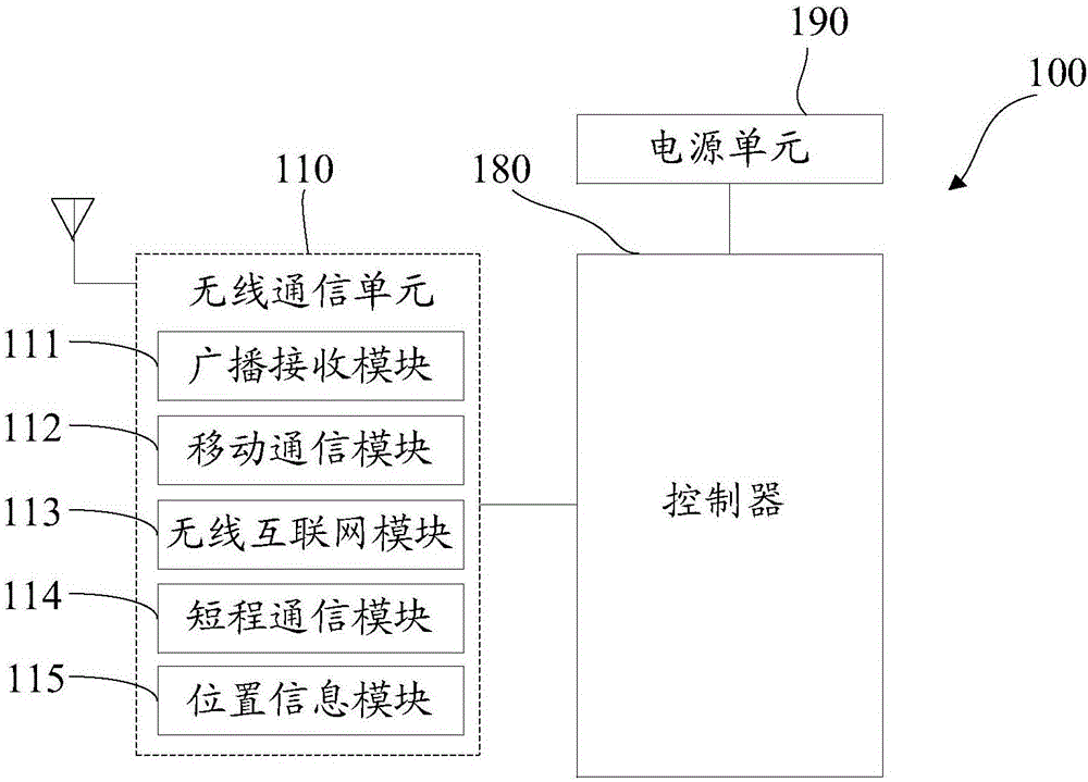
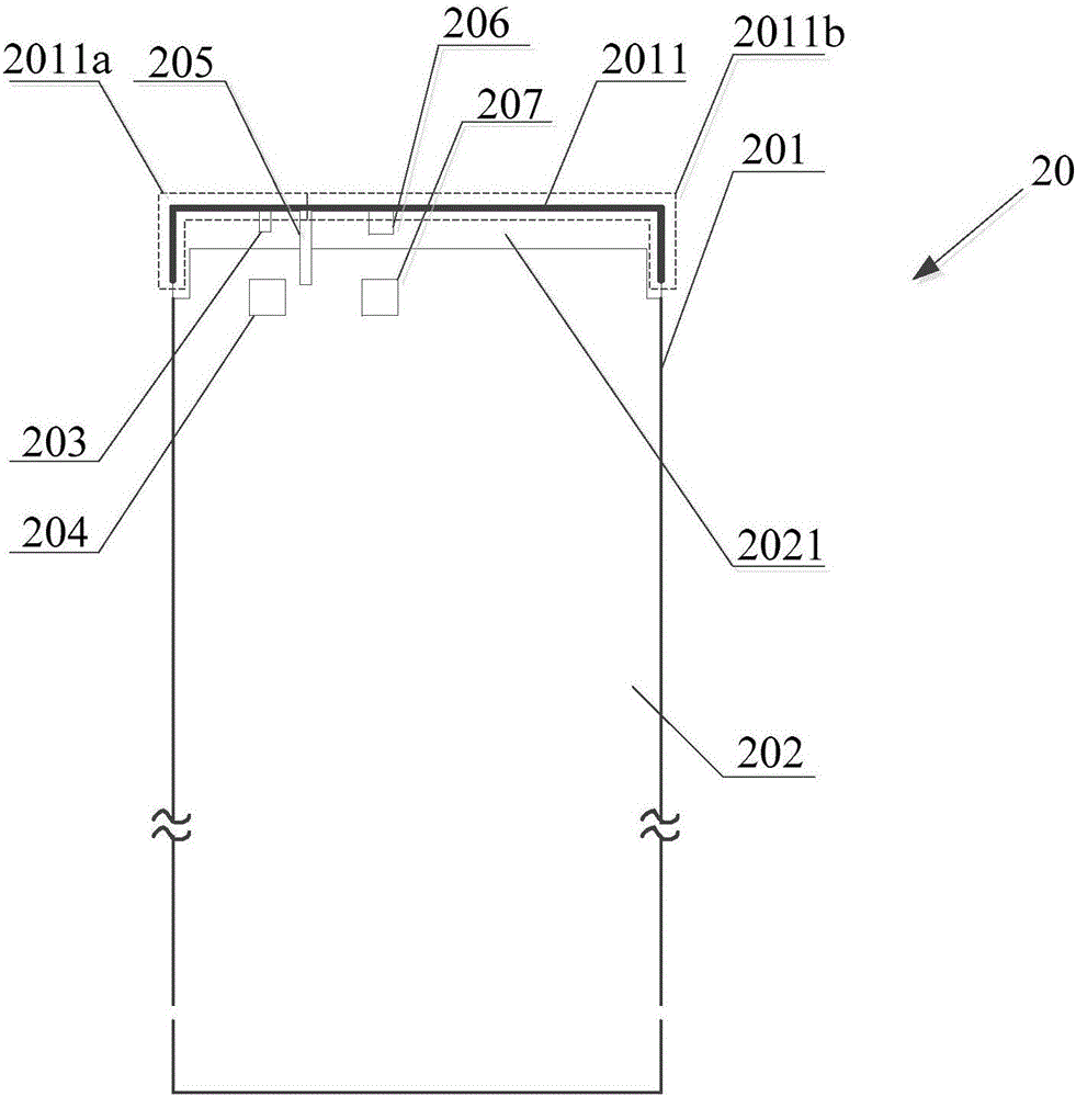

Image

  • Terminal
  • Terminal
  • Terminal

Examples


Embodiment 1

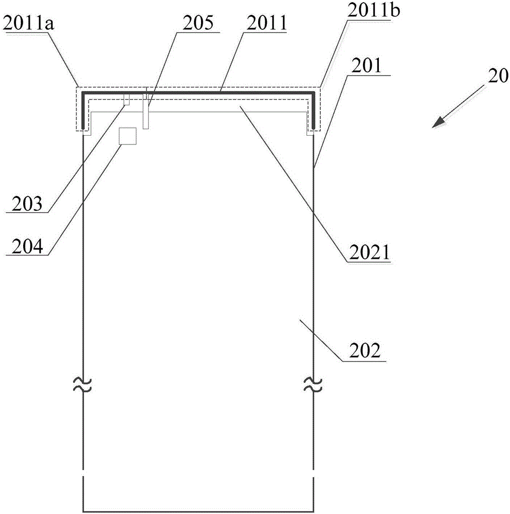
[0061] An embodiment of the present invention provides a terminal 20. The terminal 20 may include a mobile phone, a tablet computer, or other devices that require an antenna. The embodiment of the present invention uses a mobile phone as an example for illustration. Such as figure 2 As shown, the terminal 20 includes: a middle frame 201 provided with an antenna radiation area 2011, a metal backplane 202 provided with a non-conductive fracture area 2021, a wireless fidelity (Wireless-Fidelity, WIFI) antenna, and a feed port of the WIFI antenna 203. A first matching and tuning circuit 204, a ground point 205 and a coupling circuit.

[0062] Wherein, the metal back plate 202 is buckled with the middle frame 201 , and the antenna radiation area 2011 is in close contact with the non-conductive fracture area 2021 . The antenna radiation area 2011 includes a first radiation area 2011a and a second radiation area 2011b. The feeding port 203 of the WIFI antenna is set in the first ra...


PUM


Abstract

The invention discloses a terminal. The terminal includes a middle frame arranged with an antenna radiation zone, a metal back plate arranged with a non-conductive breaking joint zone, a wireless fidelity (WIFI) antenna, a feed port of the WIFI antenna, a first matching and tuning circuit, a grounding point and a coupling circuit used for coupling with the WIFI antenna; the metal back plate is buckled with the middle frame, the antenna radiation zone is tightly contacted with the non-conductive breaking joint zone; the antenna radiation zone comprises a first radiation zone and a second radiation zone, wherein the first radiation zone is provided with the feed port of the WIFI antenna, and the first radiation zone is used for radiating the signal of the WIFI antenna; the first matching and tuning circuit is arranged on a main board of a printed circuit board (PCB), and used for matching and / or tuning the signal entering the feed port of the WIFI antenna; the grounding point is arranged between the first radiation zone and the second radiation zone, and used for connecting the antenna radiation zone with the metal back plate. According to the embodiment of the invention, the terminal realizes the integration of the metal shell while ensures performance of the terminal antenna and improves the user experience.

Description

technical field [0001] This article involves but is not limited to signal transmission technology, especially a terminal. Background technique [0002] With the continuous development of electronic products, when users choose mobile phones, they not only pay attention to the call performance of mobile phones, but also pay more and more attention to the aesthetics of mobile phones, especially the low-key and luxurious consumption concept pursued by users, which makes metal texture items popular among young people. Loved by a generation of users. However, the all-metal casing will cause difficulty in mobile phone signal overflow, and the three-stage metal casing can effectively deal with the problem of mobile phone signal overflow, so it has become a trend in mobile phone design. [0003] In the related art, the upper end of the three-stage metal shell is provided with a non-conductive seam area. In order to ensure the area of ​​the antenna headroom and achieve good signal ov...

Claims


Application Information

Patent Timeline
Patent Type & Authority Applications(China)
IPC IPC(8): H01Q1/24H01Q1/50
CPCH01Q1/242H01Q1/50
Inventor 陈龙李隽
Owner NUBIA TECHNOLOGY CO LTD
Learn More