Height adjustable PCB clamping device
A PCB board and clamping device technology, applied in the field of height-adjustable PCB board clamping devices, can solve the problems of inconvenient size change, unchangeable height, low operation efficiency, etc., and achieve convenient connection to a PCB board collection device or a conveying device. , the effect of improving production efficiency
- Summary
- Abstract
- Description
- Claims
- Application Information
AI Technical Summary
Problems solved by technology
Method used
Image

Examples
Embodiment 1
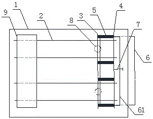
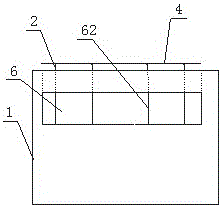
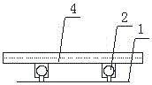
[0032] Figure 1 to Figure 4 Shows a height-adjustable PCB board clamping device provided by this embodiment, which includes a workbench 1, a guide rail 2, a clamping plate, and a board exit channel 6, wherein,
[0033] The guide rail 2 is fixed on the workbench 1. One end of the guide rail 2 is provided with a placement machine 9, and the board exit channel 6 is provided on the workbench 1 below the other end of the guide rail 2. The guide rails 2 are provided with more than two sets, all parallel to each other, The guide rail 2 is slidably connected with a splint, the splint is arranged in a direction perpendicular to the rail 2 and crosses all the rails 2;
[0034] The splint includes a first splint 4 and a second splint 3 that are parallel to each other. The first splint 4 and the second splint 3 are connected by a spring 5, and the springs 5 are parallel to the guide rail 2;
[0035] A magnet 8 is also fixed on the worktable 1, and the magnet is located at one end of the boar...
Embodiment 2
[0039] Figure 1 to Figure 4 Shows a height-adjustable PCB board clamping device provided by this embodiment, which includes a workbench 1, a guide rail 2, a clamping plate, and a board exit channel 6, wherein,
[0040] The guide rail 2 is fixed on the workbench 1. One end of the guide rail 2 is provided with a placement machine 9, and the board exit channel 6 is provided on the workbench 1 below the other end of the guide rail 2. The guide rails 2 are provided with more than two sets, all parallel to each other, The guide rail 2 is slidably connected with a splint, the splint is arranged in a direction perpendicular to the rail 2 and crosses all the rails 2;
[0041] The splint includes a first splint 4 and a second splint 3 that are parallel to each other. The first splint 4 and the second splint 3 are connected by a spring 5, and the springs 5 are parallel to the guide rail 2;
[0042] A magnet 8 is also fixed on the worktable 1, and the magnet is located at one end of the boar...
Embodiment 3
[0047] Figure 1 to Figure 4 Shows a height-adjustable PCB board clamping device provided by this embodiment, which includes a workbench 1, a guide rail 2, a clamping plate, and a board exit channel 6, wherein,
[0048] The guide rail 2 is fixed on the workbench 1. One end of the guide rail 2 is provided with a placement machine 9, and the board exit channel 6 is provided on the workbench 1 below the other end of the guide rail 2. The guide rails 2 are provided with more than two sets, all parallel to each other, The guide rail 2 is slidably connected with a splint, the splint is arranged in a direction perpendicular to the rail 2 and crosses all the rails 2;
[0049] The splint includes a first splint 4 and a second splint 3 that are parallel to each other. The first splint 4 and the second splint 3 are connected by a spring 5, and the springs 5 are parallel to the guide rail 2;
[0050] A magnet 8 is also fixed on the worktable 1, and the magnet is located at one end of the boar...
PUM
 Abstract
Description
Claims
Application Information
 - R&D
- Intellectual Property
- Life Sciences
- Materials
- Tech Scout
- Unparalleled Data Quality
- Higher Quality Content
- 60% Fewer Hallucinations
Browse by: Latest US Patents, China's latest patents, Technical Efficacy Thesaurus, Application Domain, Technology Topic, Popular Technical Reports.
© 2025 PatSnap. All rights reserved.Legal|Privacy policy|Modern Slavery Act Transparency Statement|Sitemap|About US| Contact US: help@patsnap.com