A method for manufacturing printed circuit boards using enhanced semi-additive method
A technology of semi-additive method and manufacturing method, which is applied in the direction of printed circuit, printed circuit manufacturing, conductive pattern formation, etc., and can solve the problems of low dry film thickness and limited line thickness, etc.
- Summary
- Abstract
- Description
- Claims
- Application Information
AI Technical Summary
Problems solved by technology
Method used
Image
Examples
Embodiment 1
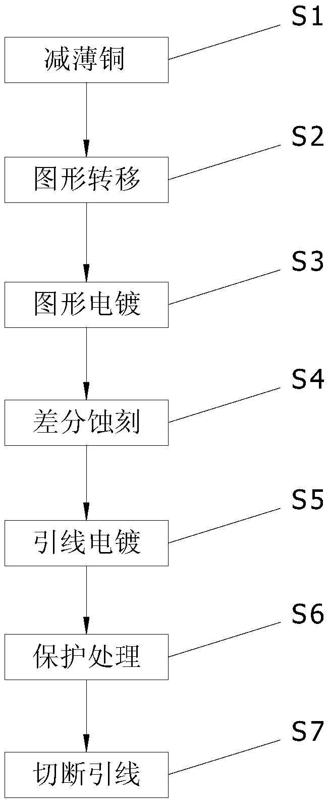
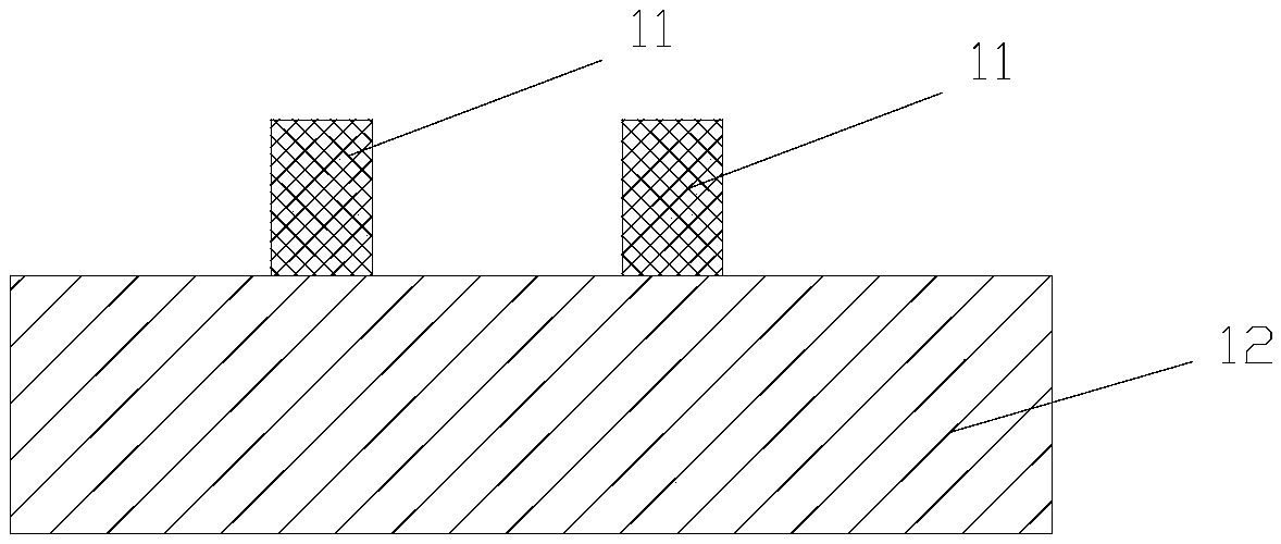
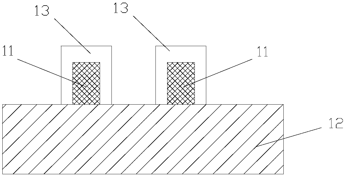
[0036] see Figure 1 to Figure 3 , a method of manufacturing a printed circuit board using an enhanced semi-additive method of the present embodiment, comprising the following steps:
[0037] Step S1: Copper Thinning
[0038] Prepare a double-sided copper-clad laminate, which has copper layers on both sides of the insulating substrate. The thickness of the insulating substrate is 50 μm, and the copper thickness is 12 μm. After cutting the double-sided copper-clad laminate, the size is 250×210mm 2 .
[0039] Copper thinning treatment is carried out on the copper clad laminate, and the copper thinning treatment is carried out with acidic copper reducing potion, so that the thickness of the copper layer is reduced to 5 μm.
[0040] Make through holes on the thinned copper clad laminate by mechanical drilling and laser drilling; the hole diameter is 100 μm, and then remove the residue and stains in the holes.
[0041] The copper-clad laminate is first processed through the blac...
Embodiment 2
[0056] The steps of this embodiment are basically the same as those of Embodiment 1, the difference is that this embodiment uses a single-sided copper clad laminate, the thickness of the insulating substrate is 50 μm, and the copper thickness is 12 μm; the copper thinning treatment is carried out by mechanical means, so that the thickness of the copper layer Thinning to 7 μm, the mechanical method is grinding or polishing; the blind hole is made by laser drilling on the thinned copper clad laminate, and the diameter of the blind hole is 150 μm; when making the electroplating seed layer, first use electroless copper, Make the copper thickness greater than 3μm, and then flash-plate until the copper thickness reaches 5~7μm; use a dry film with a thickness of 20 μm, and the line thickness in the pattern plating step is 20 μm, and after differential etching, the line width in the circuit pattern is 5 μm , the line spacing is 33 μm, and the line height is 20 μm; after lead plating, t...
Embodiment 3
[0058] The steps of this embodiment are basically the same as those of Embodiment 1, the difference is that this embodiment uses double-sided copper clad laminates, the thickness of the insulating substrate is 50 μm, and the copper thickness on both sides is 12 μm; the copper thinning treatment adopts acidic chemical copper reduction To reduce the thickness of the copper layer to 1 μm; make through holes on the thinned copper clad laminate by laser drilling; when making the electroplating seed layer, first use electroless copper to make the copper thickness greater than 3 μm, and then flash Plating until the copper thickness reaches 5-7 μm; using a dry film with a thickness of 20 μm, the thickness of the line in the pattern plating step is 25 μm, and after differential etching, the line width in the circuit pattern is 20 μm, the line spacing is 112 μm, and the line height is 20 μm. μm; after lead plating, the line width is 32 μm, the line spacing is 100 μm (500% of the dry film...
PUM
 Abstract
Description
Claims
Application Information
 - R&D
- Intellectual Property
- Life Sciences
- Materials
- Tech Scout
- Unparalleled Data Quality
- Higher Quality Content
- 60% Fewer Hallucinations
Browse by: Latest US Patents, China's latest patents, Technical Efficacy Thesaurus, Application Domain, Technology Topic, Popular Technical Reports.
© 2025 PatSnap. All rights reserved.Legal|Privacy policy|Modern Slavery Act Transparency Statement|Sitemap|About US| Contact US: help@patsnap.com


