A shoe airing rack

A technology of drying shoes and baffles, applied in the field of shoe drying racks, which can solve the problems of inconvenient drying of shoes, and achieve the effect of facilitating ventilation and protecting the environment and sanitation

Inactive Publication Date: 2017-01-11
李晋
View PDF0 Cites 0 Cited by
  • Summary
  • Abstract
  • Description
  • Claims
  • Application Information

AI Technical Summary

Problems solved by technology

[0003] In order to solve the inconvenient problem of dryin

Method used


Image

  • A shoe airing rack

Examples


Embodiment 1

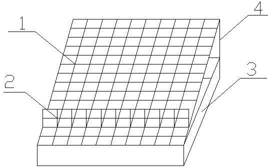
[0013] like figure 1 As shown, a shoe drying rack includes a shoe drying board 1, a baffle plate 2, a water tank 3 and a support rod 4, wherein the baffle plate 2 is arranged on the shoe drying board 1, and the bottom end of the shoe drying board 1 is connected to the side of the water tank 3 Side is hinged, and the upper end of shoe drying board 1 is hinged with support bar 4, and the bottom end of support bar 4 falls in the water tank 3.

[0014] Baffle plate 2 is arranged on the 1 / 4 place apart from the bottom of shoe-drying plate 1, and shoe-drying plate 1 and baffle plate 2 are metal grids or plastic grids, and support rod 4 is a telescopic rod.

[0015] The beneficial effects of the invention are: the shoes are placed obliquely to allow the water in the shoes to flow out; the grid is convenient for ventilation and is conducive to drying the shoes quickly; the water tank can collect the water flowing out of the shoes to protect the environment and sanitation.


PUM


Abstract

The invention provides a shoe airing rack and belongs to the field of articles of daily use. The shoe airing rack is used for solving the problem that shoe airing is inconvenient. The shoe airing rack comprises a shoe airing plate, a baffle plate, a water tank and support rods. The baffle plate is arranged on the shoe airing plate; the bottom end of the shoe airing plate is hinged to one side of the water tank; the support rods are hinged to the upper end of the shoe airing plate; the bottom ends of the support rods are located in the water tank. Shoes can be placed in an inclined manner to make water therein flow out; the screen structure facilitates ventilation, so that shoes can be aired quickly; the water tank can collect water flowing out of shoes and protect environmental cleanness.

Description

technical field [0001] The invention relates to the field of daily necessities, in particular to a shoe drying rack. Background technique [0002] In life, clothes drying racks are often used, but there are no shoe drying racks available. People have brushed their shoes and usually put them on the balcony or on the window sill. Laying the shoes flat is not conducive to the water flowing out, and the shoes are also very slow to dry; in addition, the shoes are placed on the balcony, and the water flowing out makes the ground very dirty. Contents of the invention [0003] In order to solve the inconvenient problem of drying shoes, the invention provides a shoe drying rack. [0004] The technical solution of the present invention is: a shoe drying rack, which is characterized in that it includes a shoe drying board, a baffle, a water tank and a support rod, wherein the baffle is arranged on the shoe drying board, and the bottom of the shoe drying board is connected to the sid...

Claims


Application Information

Patent Timeline
IPC IPC(8): A47G25/00
Inventor 李晋
Owner 李晋
Why Eureka
Try Eureka