Environment-friendly crushing device

A pulverizing device, an environmentally friendly technology, applied in mixers with rotary stirring devices, transportation and packaging, dissolving and other directions, can solve the problems of reduced production efficiency, affecting pulverization accuracy, etc., to extend service life, improve production efficiency, maintain internal effect of temperature

Inactive Publication Date: 2021-06-04
栗相民
View PDF1 Cites 0 Cited by
  • Summary
  • Abstract
  • Description
  • Claims
  • Application Information

AI Technical Summary

Problems solved by technology

[0006] Aiming at the deficiencies of the existing technology, the present invention provides an environmentally friendly crushing device, which solves the problem that

Method used


Image

  • Environment-friendly crushing device
  • Environment-friendly crushing device
  • Environment-friendly crushing device

Examples


Embodiment 1

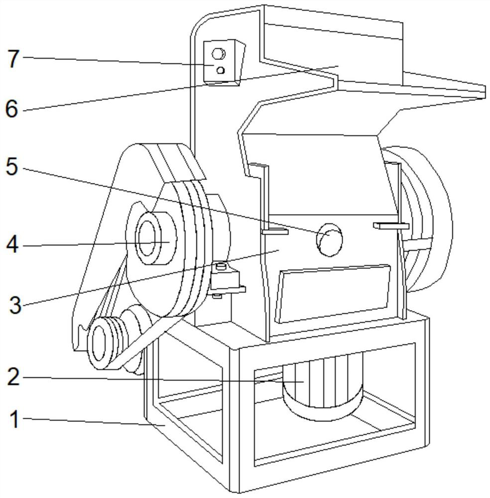
[0033] see Figure 1-2 , the present invention provides a technical solution: an environmentally friendly crushing device, including a base 1, a stirring motor 2 is provided in the middle of the top of the inner cavity of the base 1, a crushing device 3 is fixedly connected to the top of the base 1, and the front bottom of the crushing device 3 A water inlet 5 is provided in the middle position, a power mechanism 4 is provided at the bottom of both sides of the outer wall of the crushing device 3, a controller 7 is fixedly connected to the middle position of the top of the left outer wall of the crushing device 3, and a feed inlet is provided at the top of the front of the crushing device 3 6.

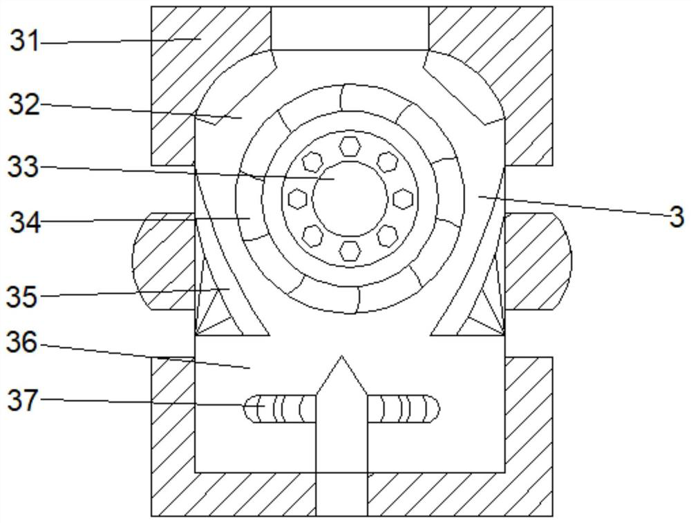
[0034] Wherein, the pulverizing device 3 comprises a casing 31, a stirring rod 37 is arranged at the bottom middle of the inner cavity bottom of the casing 31, and a collecting chamber 36 is arranged at the bottom of the inner cavity of the casing 31 at both sides of the stirring rod 3...

Embodiment 2

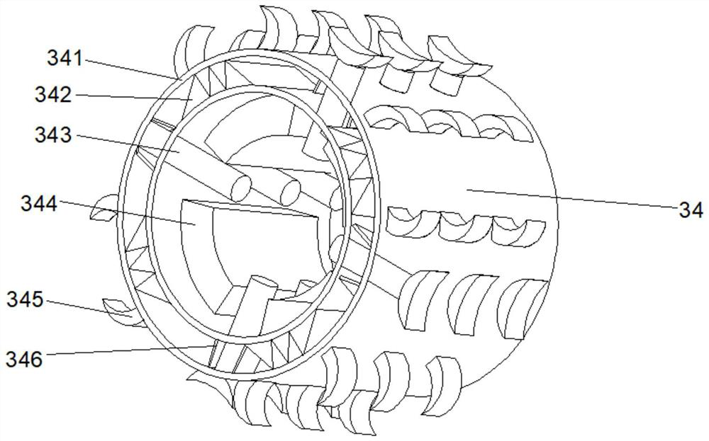
[0037] see Figure 1-4On the basis of Embodiment 1, the present invention provides a technical solution: the crushing mechanism 34 includes a crushing frame 341, the inner surface of the crushing frame 341 is provided with an auxiliary mechanism 343, and the top of the auxiliary mechanism 343 penetrates the crushing frame 341 and extends to the crushing frame 341. The outside of frame 341, the outer surface of crushing frame 341 is positioned at the both sides of auxiliary mechanism 343 and is fixedly connected with cutter 345, and the inner cavity of crushing frame 341 is positioned at the both sides of auxiliary mechanism 343 and is fixedly connected with protective plate 346, and the inner chamber of crushing frame 341 The bottom is located on both sides of the protective plate 346 and is fixedly connected with a pressure block 342 , and the inner surface of the crushing frame 341 is located on both sides of the auxiliary mechanism 343 and is fixedly connected with a linkage...

Embodiment 3

[0041] see Figure 1-6 , on the basis of Embodiment 1 and Embodiment 2, the present invention provides a technical solution: the connection mechanism d4 includes a blocking plate d45, the bottom of the inner wall on both sides of the blocking plate d45 is fixedly connected with a clamping rod d44, and the left side of the blocking plate d45 The inner wall is fixedly connected with connecting teeth d43, the inner wall on the right side of the blocking plate d45 is fixedly connected with the linkage frame d41, and the blocking plate d45 is located on both sides of the linkage frame d41 and fixedly connected with the limit block d42.

[0042] Wherein, the linkage frame d41 includes a movable rod t1, a rubber block t4 is fixedly connected to the middle of the movable rod t1, a top plate t3 is fixedly connected to the top of the rubber block t4, and a contact block t2 is arranged on the top of the top plate t3.

[0043] When in use, the inside of the device shrinks and clamps when ...


PUM


Abstract

The invention discloses an environment-friendly crushing device, which comprises a base, a stirring motor is arranged in the middle of the top of an inner cavity of the base, a crushing device body is fixedly connected to the top of the base, a water inlet is formed in the middle of the bottom of the front face of the crushing device body, power mechanisms are arranged at the bottoms of the outer walls of the two sides of the crushing device body, a controller is fixedly connected to the middle position of the top of the outer wall of the left side of the crushing device body, and a feeding port is formed in the top of the front face of the crushing device body. The invention relates to the technical field of environment-friendly equipment. According to the environment-friendly crushing device provided by the invention, crushed chippings are guided and collected through a guiding plate, crushing and collecting are more comprehensive, the internal space is saved, the situation that the inner wall adheres to the chippings is avoided, the production efficiency is improved, water circulation can be conducted in a collecting cavity, therefore the internal temperature can be kept, and the chippings can be fully soaked through stirring, internal ventilation treatment is facilitated, and the problem that the crushing speed is affected by too high temperature is solved.

Description

technical field [0001] The invention relates to the technical field of environmental protection equipment, in particular to an environmental protection crushing device. Background technique [0002] Environmental protection equipment refers to mechanical products, structures and systems manufactured and built by production units or construction installation units for controlling environmental pollution and improving environmental quality. There are many paper products, such as napkins, copy paper, books, etc. Both need logs as raw materials, and a large amount of paper requires a large number of felled trees, which will greatly increase the burden on the environment in the long run, and after a large number of felled trees will cause desertification. [0003] According to the Chinese Patent No. CN110616582A, an environmentally friendly waste paper recycling treatment device can mix waste paper and water while crushing waste paper through the mutual cooperation of crushing pa...

Claims


Application Information

Patent Timeline
IPC IPC(8): B02C18/14B02C18/18B02C23/04B02C23/18B01F7/18
CPCB02C18/0084B02C18/14B02C18/18B02C23/04B02C23/18B01F27/808B01F27/90
Inventor 栗相民
Owner 栗相民
Why Eureka
Try Eureka