
Multi-joint robot

A multi-joint robot and swing mechanism technology, applied in the field of robotics, can solve the problems of high price of steering gear, failure of steering gear performance to meet the use requirements, increase of production cost of mannequin robots, etc., and achieve the effect of reducing costs

Active Publication Date: 2017-01-11
HIT ROBOT GRP SHANGHAI CO LTD
View PDF8 Cites 10 Cited by
  • Summary
  • Abstract
  • Description
  • Claims
  • Application Information

AI Technical Summary

Problems solved by technology

[0002] In terms of clothing display methods, clothing models have formed two types: professional models and prosthetic models. The prosthetic models are worn by models imitating the human body and display clothing in a fixed posture. They are widely used in shop windows and booths, and the cost is relatively low. , can continue to display clothing for a long time, but because the prosthetic model cannot simulate the wearing effect under dynamic conditions, and cannot cause a strong visual impact on consumers to enhance the desire to buy
[0003] Therefore, in order to solve the above-mentioned problems, the existing clothing models adopt dynamic clothing models, such as the Chinese patent publication 2015105011702 "a sixteen-degree-of-freedom clothing model robot", which drives each joint to rotate through the steering gear to reach the clothing model. Dynamic effect, the current performance of domestic steering gear can not meet the requirements of use, while the price of imported steering gear is higher, which will increase the production cost of model robots

Method used


Image

  • Multi-joint robot
  • Multi-joint robot
  • Multi-joint robot

Examples


Embodiment Construction

[0032] The following description serves to disclose the present invention to enable those skilled in the art to carry out the present invention. The preferred embodiments described below are only examples, and those skilled in the art can conceive of other obvious modifications. The basic principles of the present invention defined in the following description can be applied to other embodiments, variations, improvements, equivalents and other technical solutions without departing from the spirit and scope of the present invention.

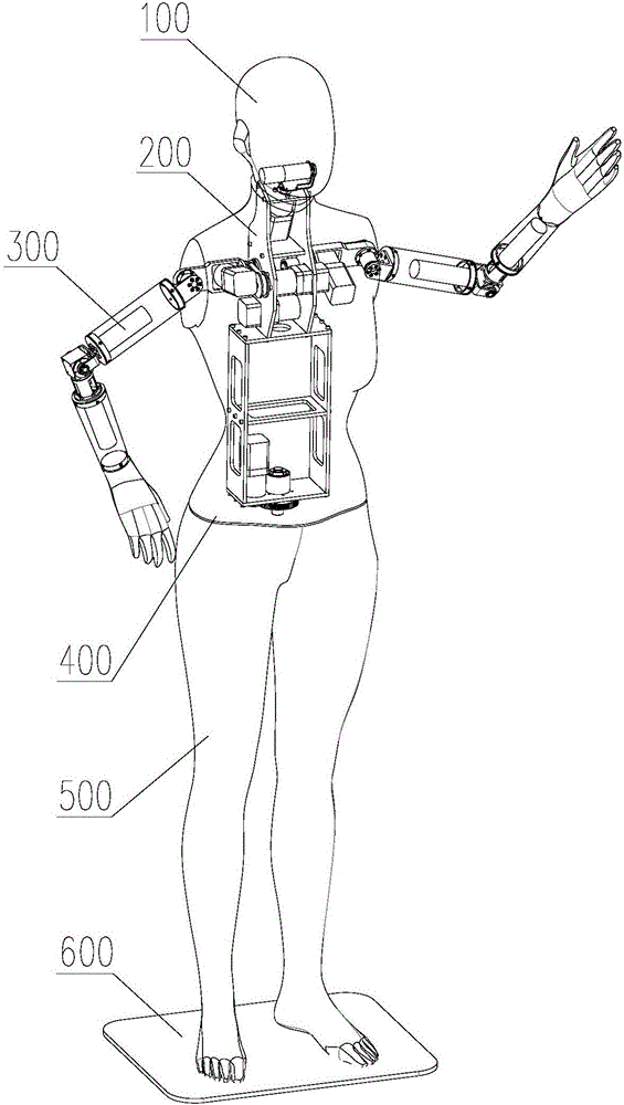
[0033] The multi-joint robot of the present invention mainly includes an upper body shell 400 and an arm shell 300, and the head shell 100 and the lower body shell 500 connected with the upper body shell 400 can be selectively installed according to actual conditions.

[0034] see figure 1 and Figure 4, shows a multi-joint robot according to a preferred embodiment of the present invention, including an upper body shell 400 and two arm shells 30...


PUM


Abstract

The invention discloses a multi-joint robot, and belongs to the field of robots. The multi-joint robot comprises an upper body shell and two arm shells. Each arm shell comprises a big arm shell body and a small arm shell body, wherein the first end of the big arm shell body is connected with the upper body shell, and the second end of the big arm shell body is connected with the small arm shell body through a first rotating and swinging mechanism; a first motor of the first rotating and swinging mechanism drives the small arm shell body to rotate around an output shaft of the first motor for simulating the rotating motion of the elbow joint of a human body and has one degree of freedom; and a second motor of the first rotating and swinging mechanism drives the small arm shell body to rotate around an output shaft of a reverser for simulating the swing motion of the elbow joint of the human body and has one degree of freedom. In this way, each arm joint of the multi-joint robot has two degrees of freedom; and direct-current brushless planetary gear motors are used as the first motors and the second motors, so that the cost of the multi-joint robot is not as high as the cost of an existing multi-joint robot provided with a steering engine, and the multi-joint robot has the functions of the existing multi-joint robot.

Description

technical field [0001] The invention relates to the field of robots, in particular to a multi-joint robot. Background technique [0002] In terms of clothing display methods, clothing models have formed two types: professional models and prosthetic models. The prosthetic models are worn by models imitating the human body and display clothing in a fixed posture. They are widely used in shop windows and booths, and the cost is relatively low. , can continue to display clothing for a long time, but because the prosthetic model cannot simulate the wearing effect under dynamic conditions, and cannot cause a strong visual impact to consumers to enhance the desire to buy. [0003] Therefore, in order to solve the above-mentioned problems, the existing clothing models adopt dynamic clothing models, such as the Chinese patent publication 2015105011702 "a sixteen-degree-of-freedom clothing model robot", which drives each joint to rotate through the steering gear to reach the clothing ...

Claims


Application Information

Patent Timeline
IPC IPC(8): B25J9/00B25J9/08B25J17/02B25J11/00A47F8/02
CPCA47F8/02B25J9/0006B25J9/08B25J11/008B25J17/0266
Inventor 刘宿东张兆东
Owner HIT ROBOT GRP SHANGHAI CO LTD
Learn More