Engine brake execution mechanism and engine

An engine braking and actuator technology, applied in engine components, machine/engine, valve control, etc., can solve problems such as engine braking failure, limit failure, engine braking actuator failure, etc.

Inactive Publication Date: 2017-01-11
WEICHAI POWER CO LTD
View PDF5 Cites 1 Cited by
  • Summary
  • Abstract
  • Description
  • Claims
  • Application Information

AI Technical Summary

Problems solved by technology

[0005] However, relying on the limit pin 3 to limit the stroke of the actuator piston 1, when the oil pressure on the actuator piston 1 is high, the reliability of the limit pin 3 is poor, and the problem of limit failure is prone to occur, which in turn leads to engine brake failure The problem
[0006] Therefore, how to solve the problem that the engine braking actuator is prone to failure in the prior art has become an important technical problem to be solved by those skilled in the art

Method used


Image

  • Engine brake execution mechanism and engine
  • Engine brake execution mechanism and engine
  • Engine brake execution mechanism and engine

Examples


Embodiment Construction

[0025] This specific embodiment provides an engine brake actuator, which can avoid the problem of failure of the limit of the actuator piston. The specific embodiment also provides an engine comprising the above-mentioned engine braking actuator.

[0026] Hereinafter, an embodiment will be described with reference to the drawings. In addition, the examples shown below do not limit the content of the invention described in the claims in any way. In addition, all the contents of the configurations shown in the following embodiments are not limited to be essential to the solution of the invention described in the claims.

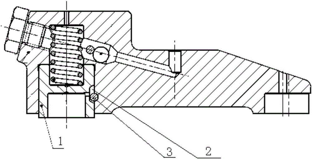
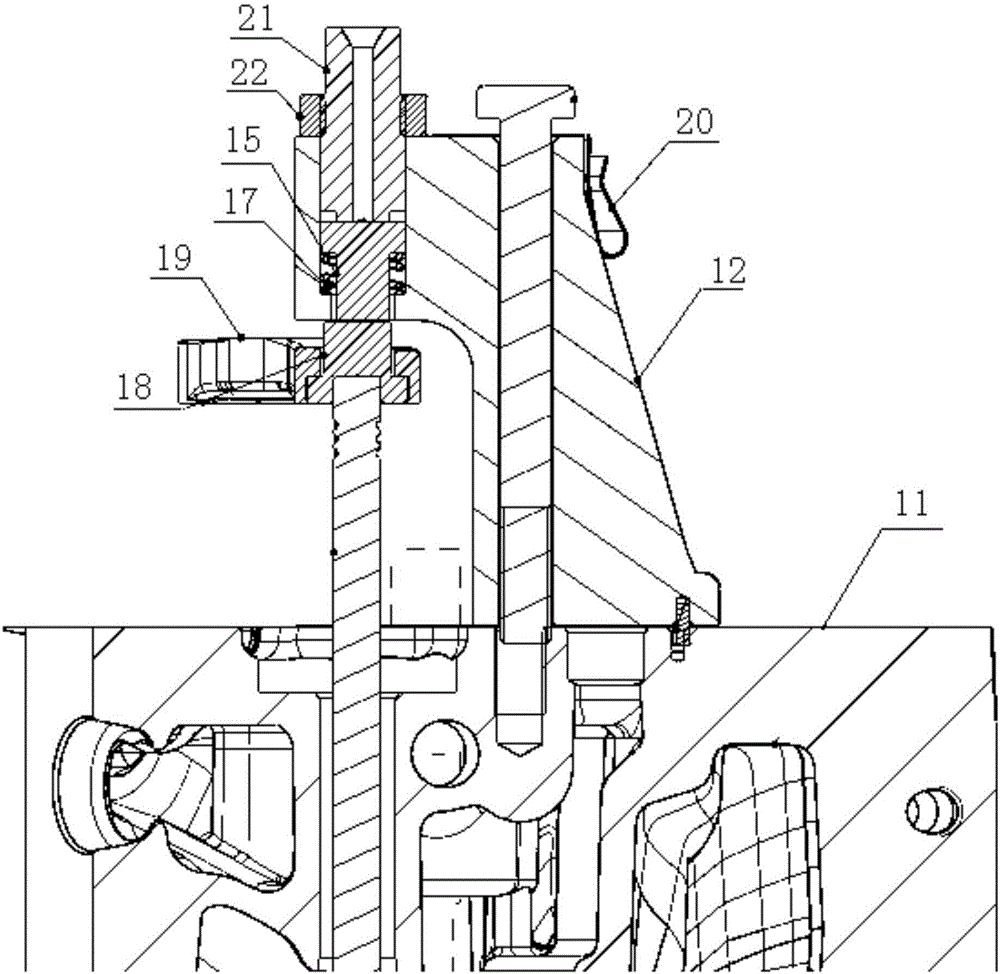
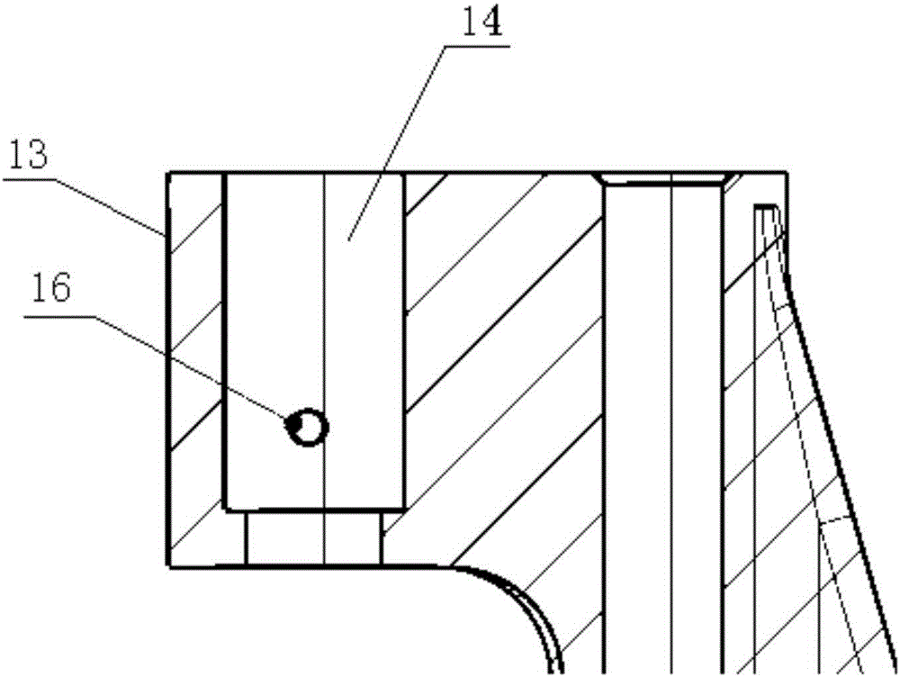
[0027] Please refer to figure 2 with image 3 , The engine brake actuator provided in this embodiment includes a bracket 12 fixed on the cylinder head 11 of the engine. Specifically, the bracket 12 can be installed on the cylinder head 11 of the engine through positioning pins and bolts. Wherein, the bracket 12 includes an extension portion 13 extending ab...


PUM


Abstract

The invention discloses an engine brake execution mechanism and an engine. The engine brake execution mechanism comprises a support fixed to a cylinder cover of the engine, the support comprises an extending portion extending to the position above an air valve, the extending portion is provided with a through hole allowing the extending portion to penetrate in the vertical direction, an execution piston is arranged in the through hole in a sliding manner, the upper end of the execution piston is communicated with a pressure oil supply pipeline, the lower end of the execution piston is connected with a linkage part for controlling the lift of the air valve, and an elastic part is arranged between the wall of the through hole and the execution piston; an oil draining hole is formed in the side wall of the through hole, and when the execution piston displaces to the preset position downwards, the pressure oil is communicated with the oil draining hole, the execution piston stops downward displacement, and the lift of the air valve reaches the maximum. According to the arrangement, the engine brake execution mechanism can avoid limiting failures of the execution piston.

Description

technical field [0001] The invention relates to the technical field of engines, and more specifically relates to an engine braking actuator and an engine. Background technique [0002] When the car is going down a long slope, when the driver activates the engine braking device, the oil supply system stops supplying oil, and at the same time, when the engine is close to the top dead center in the compression stroke, the exhaust valve is opened by a small lift under the drive of the engine braking device. stroke (1-2mm), the compressed high-pressure gas in the cylinder is quickly released, and the pressure in the cylinder drops rapidly, so in the next power stroke, the engine basically does not work externally. [0003] In the prior art, the restriction on the lift of the exhaust valve is realized through a mechanical mechanism, such as figure 1 as shown, figure 1 It is an engine braking actuator in the prior art. [0004] This kind of actuator controls the lift of the exha...

Claims


Application Information

Patent Timeline
Patent Type & Authority Applications(China)
IPC IPC(8): F01L13/06F01L9/02F01L9/10
CPCF01L13/06F01L2760/003F01L9/10
Inventor 王刚乔芳乔军
Owner WEICHAI POWER CO LTD
Why Eureka
Try Eureka