Forced circulation water heater of engine

A water heater and forced circulation technology, applied in engine components, engine starting, machine/engine, etc., can solve problems such as inability to perform automatic monitoring, filter disassembly and cleaning, uncontrollable temperature, etc., to achieve compact structure, sealing The effect is good, the effect of improving the service life

Active Publication Date: 2017-01-11
SMARTGEN TECH
View PDF6 Cites 1 Cited by
  • Summary
  • Abstract
  • Description
  • Claims
  • Application Information

AI Technical Summary

Problems solved by technology

[0002] At present, when the forced circulation heater-CN201420486649.4 is in use, automatic monitoring cannot be performed, and the temperature cannot be controlled. The heating time needs to be mastered by feeling. When cleaning the coolant, it is time-consuming and laborious. The filter needs to be disassembled and cleaned, which is time-consuming and laborious.

Method used


Image

  • Forced circulation water heater of engine
  • Forced circulation water heater of engine
  • Forced circulation water heater of engine

Examples


Embodiment Construction

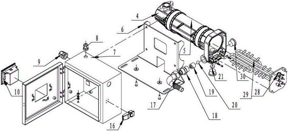
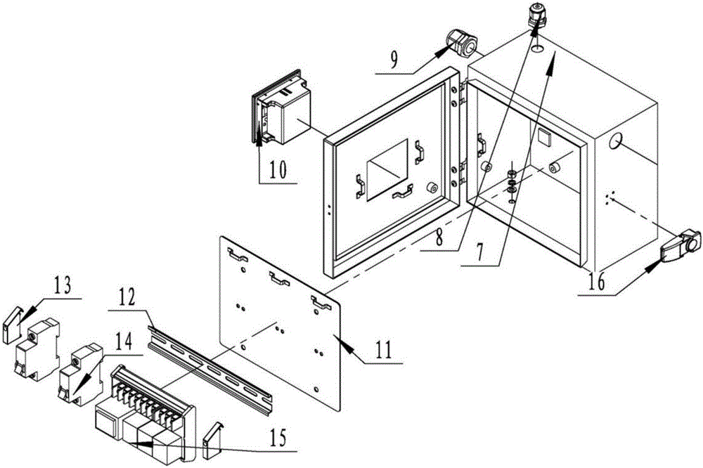
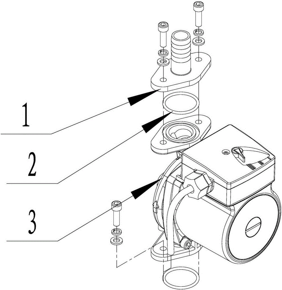
[0033] like Figure 1-6 As shown, the forced circulation engine water heater of the present embodiment includes a water pump main frame 3, a pagoda joint with flange 1 arranged at the upper end of the housing main body 5 of the main machine 3 of the water pump, a pagoda joint 1 with a flange at the lower end of the pagoda joint with a flange and the housing The O-ring 2 between the upper ports of the main body 5, the front housing 4 installed on the left side of the housing main body 5 through the hexagonal socket bolt, the rear housing 25 installed on the right end of the housing main body 5 through the hexagonal socket bolt, and the rear housing 25 installed on the rear shell The mask 24 at the right end of the body 25, the foamed silica gel sealing strip 26 arranged between the rear casing 25 and the right end surface of the casing main body 5, the L bracket 6, and the left side of the vertical plate of the L bracket 6 and the bottom of the L bracket 6 The cabinet body 7 on...


PUM


Abstract

The invention relates to a forced circulation water heater of an engine. The forced circulation water heater comprises a water pump main machine, a pagoda connector with a flange, an O-shaped ring, a front shell, a rear shell, a face film, a foaming silica gel sealing strip, an L-shaped support, a cabinet, a fixing plate and a guide rail. The pagoda connector with the flange is arranged at the upper end of a shell body of the water pump main machine. The O-shaped ring is arranged between the lower end of the pagoda connector with the flange and an upper port of the shell body. The front shell is arranged on the left side of the shell body through an inner hexagon bolt. The rear shell is arranged at the right end of the shell body through an inner hexagon bolt. The face film is arranged at the right end of the rear shell. The foaming silica gel sealing strip is arranged between the rear shell and the right end face of the shell body. The cabinet is arranged between the left side face of a vertical plate of the L-shaped support and the upper surface of the bottom of the L-shaped support. The fixing plate is arranged in the cabinet. The guide rail is arranged on the fixing plate. The forced circulation water heater is reasonable in structure, convenient to use, firm, durable, safe, reliable, reasonable in structure and capable of achieving automatic control.

Description

technical field [0001] The present invention relates to forced circulation engine water heaters. Background technique [0002] At present, when the forced circulation heater-CN201420486649.4 is in use, automatic monitoring cannot be performed, and the temperature cannot be controlled. The heating time needs to be grasped by feeling. Contents of the invention [0003] The technical problem to be solved by the present invention is to provide a forced circulation engine water heater with reasonable design, compact structure and convenient use. [0004] In order to solve the problems referred to above, the technical scheme that the present invention takes is: [0005] A water heater for a forced circulation engine, comprising a water pump main body, a pagoda joint with a flange arranged on the upper end of a housing main body of the water pump main machine, an O ring provided between the lower end of the pagoda joint with a flange and the upper port of the housing main body, ...

Claims


Application Information

Patent Timeline
IPC IPC(8): F02N19/10F01P5/10F01P11/06F01P11/02F01P7/14
CPCF01P5/10F01P7/14F01P11/0276F01P11/06F01P2007/146F01P2011/061F01P2060/18F02N19/10
Inventor 宋耀军马雷徐红宗于光枭韩珂
Owner SMARTGEN TECH
Why Eureka
Try Eureka