Supercharge Your Innovation With Domain-Expert AI Agents!

Novel vending machine delivery mechanism

A vending machine, a new type of technology, applied in the direction of instruments, coin-operated equipment for distributing discrete items, coin-operated equipment for distributing discrete items, etc., can solve the inconvenience of loading, high cost, slow delivery speed, etc. problems, to achieve the effect of compact structure, convenient loading and low cost

Inactive Publication Date: 2017-01-11
HUNAN KIMMA INTELLIGENT EQUIP MFR
View PDF12 Cites 13 Cited by
  • Summary
  • Abstract
  • Description
  • Claims
  • Application Information

AI Technical Summary

Problems solved by technology

[0003] It is necessary to install a motor at the end of the spring of each cargo lane, and the motor drives the coil spring to rotate to push the goods out. Not only is the cost high, the delivery speed is slow, and the pallet needs to be taken out when loading, and each coil between the coils needs to be taken out. The goods are placed in each space, and there are intervals between the goods and they are placed obliquely. The space utilization rate is not high, and it is inconvenient to load.
There is also a delivery method in the form of a slideway and a push slider, in order to easily push the slider back under the tension of the coil spring during loading, and the speed of the delivery of the goods should not be too fast, so as not to hit the door panel of the vending machine and cause deformation of the goods Damage and bad noise, so the tension of the coil spring should not be too large, and at the same time to ensure smooth shipment, usually adopt the method of inclined cargo lane to assist the shipment, but this leads to a decrease in space utilization

Method used


Image

  • Novel vending machine delivery mechanism
  • Novel vending machine delivery mechanism
  • Novel vending machine delivery mechanism

Examples


Embodiment Construction

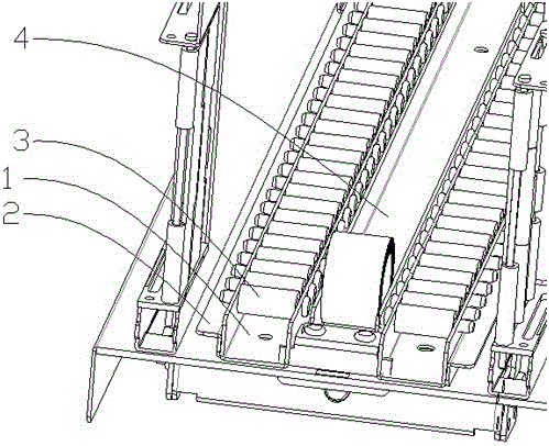
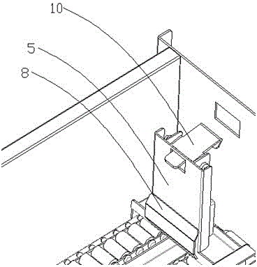
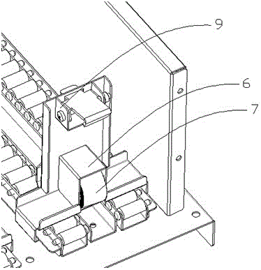
[0034] see figure 1 — Figure 8, a new type of automatic vending machine delivery mechanism of the present invention, including a tray, a push mechanism and a baffle mechanism, the tray is connected and fixed by a base, a rear seat and a partition, and the partition is installed on the base to divide the tray into several Cargo lane; the push mechanism includes a slideway part and a push plate part, the slideway in the slideway part adopts a U-shaped slideway, and a coil spring groove is arranged in the middle of the two U-shaped slideways; the push plate main body in the push plate part The front protrusion of the push plate, the coil spring box and the lock bracket are installed. A coil spring is installed in the coil spring box. One end of the coil spring stretches through the square hole at the bottom of the main body of the push plate, and is finally fixed on the front end of the coil spring slot through the coil spring slot. The lock is installed on the bracket, corresp...


PUM


Abstract

A novel vending machine delivery mechanism comprises a tray, a push mechanism and baffle mechanisms. The tray is formed by fixedly connecting a base, a back base and partition plates, and the partition plates are installed on the base to divide the tray into multiple cargo paths; the push mechanism comprises a slide path part and a push plate part, slide paths in the slide path part adopt U-shaped slide paths, and a coil spring groove is formed between the two U-shaped slide paths; a push plate protrusion, a coil spring box and a lock catch support are installed on a push plate body in the push plate part, a coil spring is installed in the coil spring box, one end of the coil spring stretches to penetrate through a square hole formed in the bottom of the push plate body, passes through the coil spring groove and is finally fixed to the front end of the coil spring groove, a lock catch is installed on the lock catch support, and a lock catch hole corresponding to the lock catch is formed in the back base of the tray; the baffle mechanisms are installed on the partition plates arranged on the two sides of the front ends of the cargo paths, and the baffle mechanisms adopt hinge baffles which are connected and driven by hinge baffle driving mechanisms. The novel vending machine delivery mechanism is compact in structure, low in cost, high in delivery efficiency, stable and reliable, cargoes can slide more easily, the tensile force of the coil spring can be reduced, inclined cargo paths are not needed, the space is saved, the tray does not need to be taken out when loading is conducted, and convenience and rapidness are achieved.

Description

technical field [0001] The invention belongs to the technical field of commercial machinery, and in particular relates to a novel delivery mechanism of an automatic vending machine. Background technique [0002] At present, the commonly used vending machine shipping method in the market is the spiral spring cargo channel, which requires [0003] It is necessary to install a motor at the end of the spring of each cargo lane, and the motor drives the coil spring to rotate to push the goods out. Not only is the cost high, the delivery speed is slow, and the pallet needs to be taken out when loading, and each coil between the coils needs to be taken out. The goods are placed in each space, there are intervals between the goods and they are placed at an angle, the space utilization rate is not high, and it is inconvenient to load. There is also a delivery method in the form of a slideway and a push slider, in order to easily push the slider back under the tension of the coil spr...

Claims


Application Information

Patent Timeline
IPC IPC(8): G07F11/00
CPCG07F11/00
Inventor 金瓯梅传根贺建飚
Owner HUNAN KIMMA INTELLIGENT EQUIP MFR
Features
  • R&D
  • Intellectual Property
  • Life Sciences
  • Materials
  • Tech Scout
  • Unparalleled Data Quality
  • Higher Quality Content
  • 60% Fewer Hallucinations
Learn More