
Relay protection current bridging device

A relay protection and current technology, which is applied to the parts of connecting devices, devices that prevent contact with live contacts, coupling devices, etc. Equipment failure rate, easy on-site use, and the effect of improving reliability

Inactive Publication Date: 2017-01-11
STATE GRID CORP OF CHINA +1
View PDF0 Cites 0 Cited by
  • Summary
  • Abstract
  • Description
  • Claims
  • Application Information

AI Technical Summary

Problems solved by technology

[0002] As people's requirements for the safety and reliability of power systems are getting higher and higher, that is, the requirements for the four properties of relay protection are getting higher and higher. From the perspective of the reliability of secondary protection, protection devices, measuring devices, metering devices, and stability The control device and the fault recording device should use independent current transformer windings. The protection configuration has more and more requirements for the configuration number of current transformer windings, but too many configurations of current transformer windings will bring great problems to the design and manufacture. Difficult, and affect the reliability of primary equipment, comprehensively consider that some relay protection devices share the current transformer winding
For a long time, one method of testing other operating protective devices connected in series after the current circuit of the tested protective device is to use the experimental power line to bridge one by one. When the current of the running protection device disappears, and the wires are easy to be entangled, it increases the danger and the probability of accidental touch for the maintenance personnel.
Another method is to use hard wires to bridge phase by phase and fasten them with screws. This method is reliable and the wires are not easily entangled, but it also increases the danger and the probability of accidental contact for maintenance personnel.
The jumper is unreliable and not firm, and a wrong touch will cause incalculable economic losses and negative impacts on the power grid

Method used


Image

  • Relay protection current bridging device
  • Relay protection current bridging device
  • Relay protection current bridging device

Examples


Embodiment

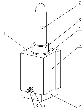
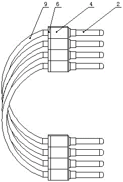
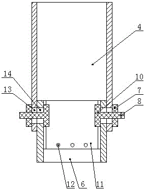
[0013] Example: such as Figure 1-3 As shown, the relay protection current crossover device includes two sets of insulating sleeves 4 connected in parallel, and a terminal 2 is fixed in each insulating sleeve 4, and the two sets of insulating sleeves 4 and the internally fixed terminals 2 correspond one-to-one, and Connected via wire 9.

[0014] The insulating sleeve 4 is a semi-closed cavity sleeve with an open lower end, and the opposite end faces of its outer wall are respectively provided with a clamping block 1 and a clamping groove 5, and the adjacent two insulating sleeves 4 pass through the clamping block 1 and the clamping groove 5. The card slots 5 are plugged and connected. This structure can flexibly select the number of insulating sleeves 4 with terminals 2, so that the three-phase and four-phase bridging operation can be completed at one time.

[0015] The upper end of the insulating sleeve 4 is sealed, and a terminal base 3 is provided on it. The connecting te...


PUM


Abstract

The invention relates to a relay protection current bridging device. The bridging device comprises two groups of parallelly connected insulation sleeves. A connection terminal is fixed in each insulation sleeve. The insulation sleeves correspond to the connection terminals fixed therein one by one and the insulation sleeves are connected with the connection terminals through wires. Each of the insulation sleeves is a semi-enclosed cavity sleeve with an opened lower end. A clamping block and a clamping groove are respectively arranged on / in opposite end faces of the outer wall of each insulation sleeve. Adjacent insulation sleeves are inserted into each other through the clamping blocks and the clamping grooves. The bridging device is simple in structure and easy to use on the spot, reliability of relay protection is improved, equipment failure rate is reduced, and the requirement for safety and stability of the grid of 220kV or over is largely met.

Description

technical field [0001] The present application relates to a relay protection current jumper used when a relay protection device under inspection shares a current transformer winding with other relay protection devices. Background technique [0002] As people's requirements for the safety and reliability of power systems are getting higher and higher, that is, the requirements for the four properties of relay protection are getting higher and higher. From the perspective of the reliability of secondary protection, protection devices, measuring devices, metering devices, and stability The control device and the fault recording device should use independent current transformer windings. The protection configuration has more and more requirements for the configuration number of current transformer windings, but too many configurations of current transformer windings will bring great problems to the design and manufacture. It is difficult and affects the reliability of the primar...

Claims


Application Information

Patent Timeline
Patent Type & Authority Applications(China)
IPC IPC(8): H01R31/06H01R13/502H01R13/44H01R13/72
Inventor 晁攸重安春香王亮杨成刚邓剑伟李红川黄培龙康文超李运杰符廷罡
Owner STATE GRID CORP OF CHINA
Learn More