
Lifting appliance upper rack, lifting mechanism and crane

A lifting mechanism and spreader technology, which is applied in the field of spreader racks, cranes, and lifting mechanisms, can solve the problems of inconsistent service life of four steel wire ropes, reduced service life of steel wire ropes, waste of steel wire ropes, etc., to save maintenance costs, improve life, Good anti-shake effect

Inactive Publication Date: 2014-09-10
SANY MARINE HEAVY IND
View PDF9 Cites 0 Cited by
  • Summary
  • Abstract
  • Description
  • Claims
  • Application Information

AI Technical Summary

Problems solved by technology

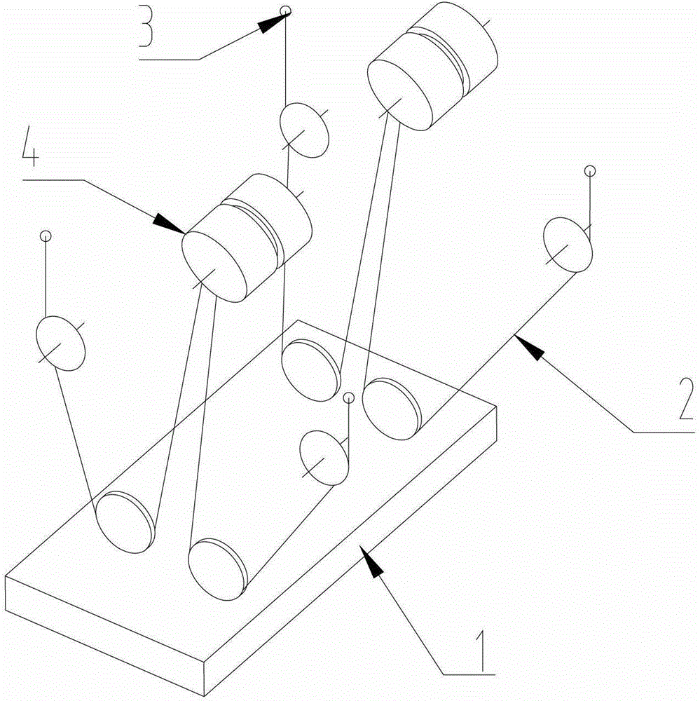
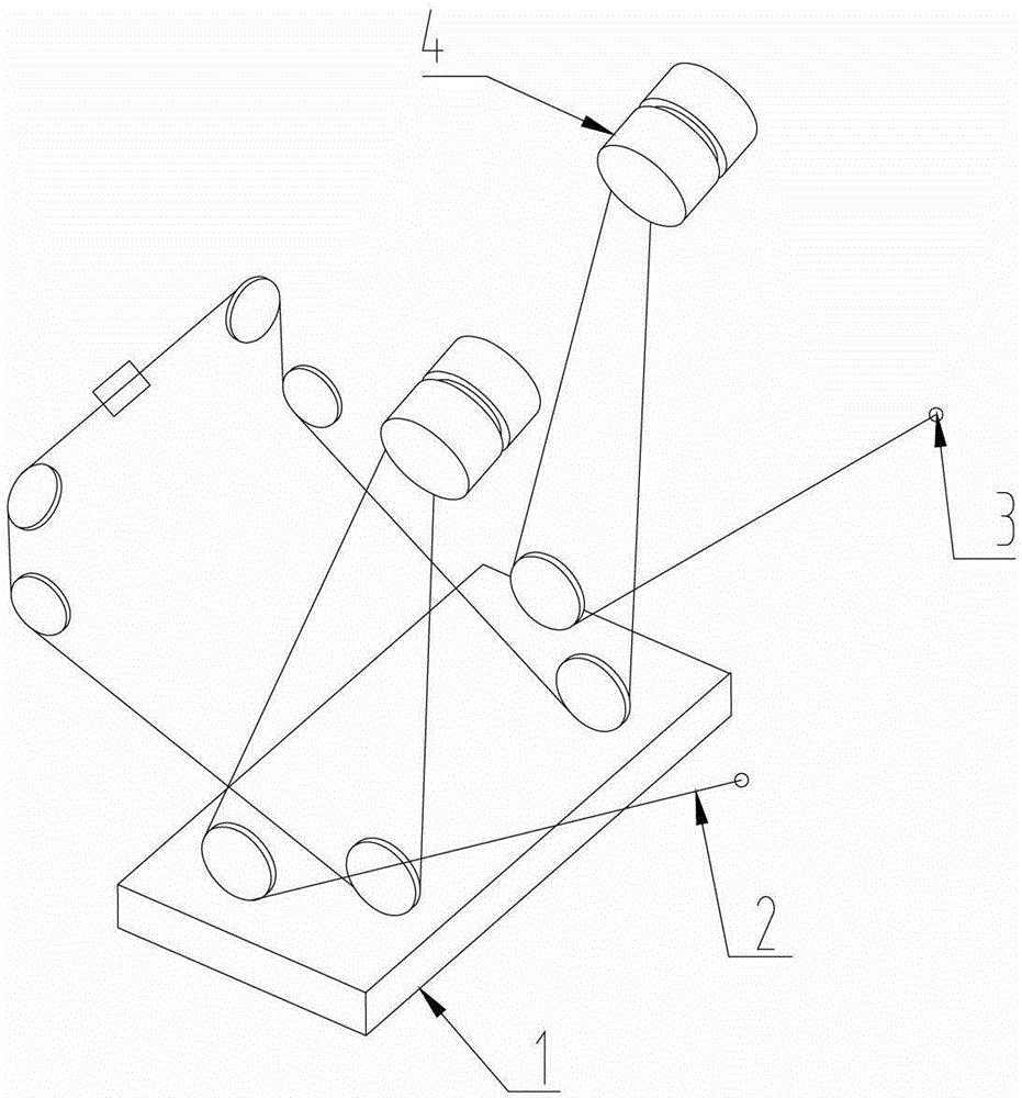
Compared with the parallel pulley rack, this upper rack has been improved to a certain extent, and the oblique angle has been significantly increased. However, in the winding system, the rewinding of the steel wire ropes 2 and 3 is still not avoided, and the service life of the rewound steel wire ropes 2 and 3 is reduced. , the service life of the four steel wire ropes 2 and 3 is inconsistent, and there is waste when replacing the steel wire ropes 2 and 3

Method used


Image

  • Lifting appliance upper rack, lifting mechanism and crane
  • Lifting appliance upper rack, lifting mechanism and crane
  • Lifting appliance upper rack, lifting mechanism and crane

Examples


Embodiment Construction

[0029] The specific implementation manners according to the present invention will be described below in conjunction with the accompanying drawings. It should be noted that, in the case of no conflict, the embodiments of the present application and the features in the embodiments can be combined with each other.

[0030] In the following description, many specific details are set forth in order to fully understand the present invention. However, the present invention can also be implemented in other ways different from those described here. Therefore, the protection scope of the present invention is not limited by the specific implementation disclosed below. Example limitations.

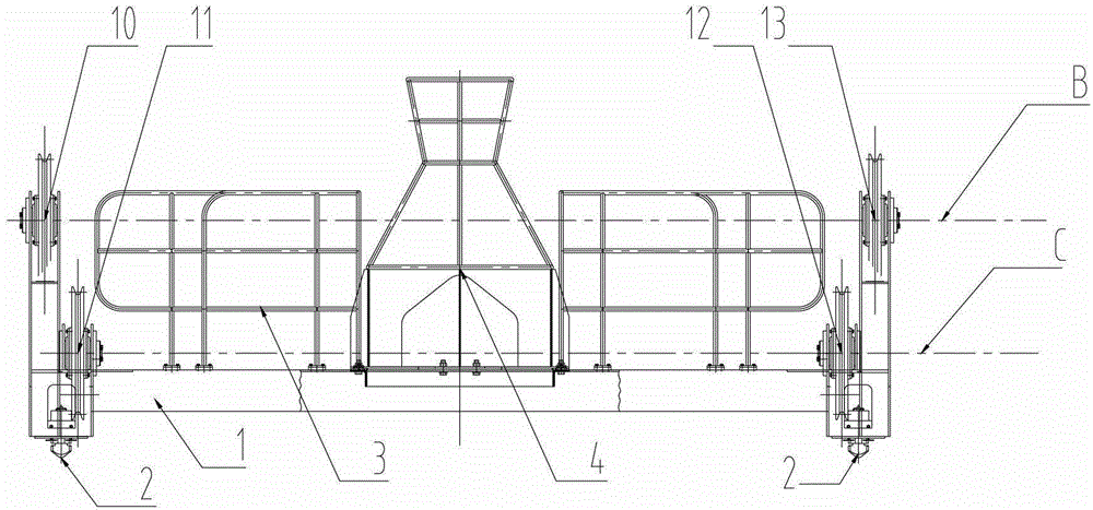
[0031] Such as image 3 and Figure 4 As shown, a spreader upper frame includes: a body 1, a first left pulley 10, a second left pulley 11, a first right pulley 13, a second right pulley 12, a guardrail 3, and 4 screw-pin devices 2 , Cable wire frame 4. The cable wire frame 4 is used to install t...


PUM


Abstract

The invention provides a lifting appliance upper rack, comprising a body, a first left pulley, a second left pulley, a first right pulley and a second right pulley. The first left pulley and the second left pulley are mounted at the left side of the body; and the first right pulley and the second right pulley are mounted at the right side of the body. The lifting appliance upper rack is characterized in that the rotation axes of the first left pulley, the second left pulley, the first right pulley and the second right pulley are located in a first vertical plane; and the first vertical plane is vertical to a horizontal plane. An inclined drawing angle of a lifting steel wire rope in a lifting mechanism using the lifting appliance upper rack reaches the maximum, so that the lifting mechanism has a better anti-rocking effect. Meanwhile, the lifting steel wire rope is prevented from being inversely wound. Therefore, the service life of the lifting steel wire rope is prolonged and the maintenance cost is lowered.

Description

technical field [0001] The invention relates to the technical field of engineering machinery, in particular to a hanger rack, a hoisting mechanism and a crane. Background technique [0002] At present, there are two relatively common types of spreader racks for crane spreaders, one is a pulley block with two pulley faces parallel on the same plane (hereinafter referred to as parallel pulley rack), and the other is on a different plane, two pulleys The pulley block placed in a dislocation on the surface (hereinafter referred to as the dislocation pulley spreader rack). [0003] Such as figure 1 Shown, the parallel pulley spreader is wound on a rack in a crane application. It can be seen from the winding diagram that there are 4 pulleys arranged on the upper frame 1 of the spreader. superior. There are two obvious deficiencies in this rack. One is that the crane using this spreader has a small oblique angle of the steel wire rope in the lifting winding system. In the syst...

Claims


Application Information

Patent Timeline
Patent Type & Authority Patents(China)
IPC IPC(8): B66D3/08B66C19/00B66C11/16
Inventor 钟礼平陈罗
Owner SANY MARINE HEAVY IND
Learn More