
Quick switching control method and control device for concentrated bypass type parallel UPS

A fast switching and control device technology, applied in the direction of circuit devices, electrical components, emergency power supply arrangements, etc., can solve the problem that the switching method cannot meet the switching time requirements, achieve fast switching action timing, fast judgment, and avoid UPS device damage Effect

Active Publication Date: 2017-01-11
XUJI GRP +5
View PDF5 Cites 3 Cited by
  • Summary
  • Abstract
  • Description
  • Claims
  • Application Information

AI Technical Summary

Problems solved by technology

[0005] The purpose of the present invention is to provide a fast switching control method of centralized bypass parallel UPS to solve the problem that the traditional switching method cannot meet the switching time requirement

Method used


Image

  • Quick switching control method and control device for concentrated bypass type parallel UPS
  • Quick switching control method and control device for concentrated bypass type parallel UPS
  • Quick switching control method and control device for concentrated bypass type parallel UPS

Examples


Embodiment Construction

[0033] The present invention will be described in further detail below in conjunction with the accompanying drawings.

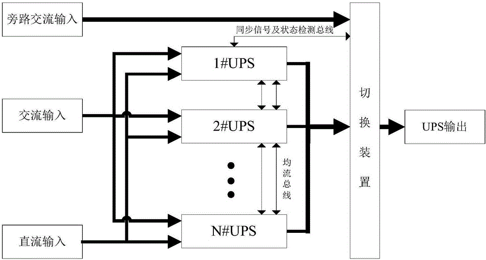
[0034] The fast switching control device of centralized bypass parallel UPS provided by the present invention is suitable for figure 1 The shown UPS system, since this system belongs to the conventional technology and has been described in detail in the background technology section, will not be described in detail here.

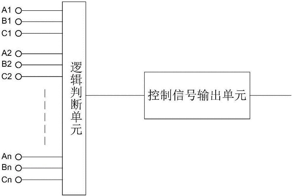
[0035] Such as image 3 As shown, the fast switching control device includes a logic judgment unit, and the logic judgment unit has n sets of signal input terminals, and each set of signal input terminals corresponds to a UPS module in the UPS system, that is to say, the UPS modules in the UPS system The number is the same as the number of groups of signal input terminals of the logic judgment unit, and each group of signal input terminals is used to input data information in the corresponding UPS module.

[0036] Each group of signal inp...


PUM


Abstract

The invention relates to a quick switching control method and a control device for a concentrated bypass type parallel UPS, and aims to detect voltage of each UPS module; at least two detection points are set in each UPS module, and respectively correspond to an alternating and direct current input end or output end in the UPS module and a middle connection line; when a voltage signal of at least one of the detection points is an abnormal signal, the UPS module is abnormal; and when all the USP modules are abnormal, an output is switched to a bypass for outputting. The control mode can accurately and quickly judge the switching operation moment, so that the judgment duration is greatly shortened, the phenomenon that the UPS output and the bypass output have short circuit for milliseconds is avoided, and the phenomena of damage to a UPS device, tripping of a bypass input switch and the like are avoided.

Description

technical field [0001] The invention relates to a fast switching control method and a control device of a centralized bypass parallel UPS. Background technique [0002] Such as figure 1 As shown, it is the centralized bypass parallel UPS system we use daily. The core components of the UPS system are two parts, the UPS power supply part and the switching device. Among them, the UPS power supply part has two power output channels for selection, one is to output AC power through the UPS device, and the other is a bypass line, which is used to directly output AC power. The bypass line is used to output electric energy as a backup power supply when the UPS device fails to output electric energy normally. Centralized bypass means that the bypass line is directly connected to the switching device, and it is two independent parts with the UPS device. The UPS device includes several UPS modules. All UPS modules share two inputs, namely AC input and DC input. For any UPS module, t...

Claims


Application Information

Patent Timeline
Patent Type & Authority Applications(China)
IPC IPC(8): H02J9/06
CPCH02J9/061
Inventor 赵启良尹强罗治军刘天强熊泽成庞浩于越苟旭丹李松涛杨浩蔡刚林杜渐黄成辰
Owner XUJI GRP
Learn More