Drip irrigation tape pick-up mechanism and fully-automatic drip irrigation tape recycling machine formed thereby
A pick-up mechanism and drip irrigation belt technology, applied in agricultural machinery and implements, harvesters, conveyor objects, etc., can solve the problems of low work efficiency, low pick-up rate, and unsatisfactory pick-up effect, and achieve the effect of reducing the degree of manual intervention.
- Summary
- Abstract
- Description
- Claims
- Application Information
AI Technical Summary
Problems solved by technology
Method used
Image

Examples
Embodiment 1
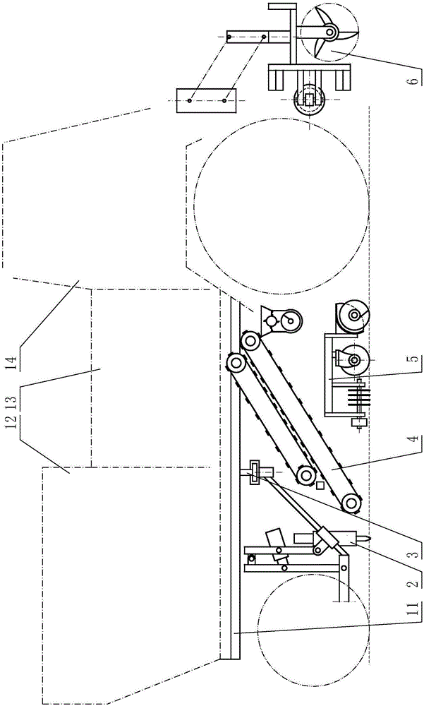
[0051] Embodiment 1: refer to Figure 1 to Figure 14 , the structural representation of the embodiment of the present invention 1 is a self-propelled full-automatic drip irrigation tape recovery machine, including power, main frame (11), transmission mechanism, drip irrigation tape collection mechanism (13), and is provided with on the main frame (11). A plurality of sets of drip irrigation tape picking mechanisms, the drip irrigation tape collection mechanism (13) is a combination of a drip irrigation tape crushing mechanism and a collection box.
[0052] The multiple groups of drip irrigation belt pick-up mechanisms are connected to the main frame (11) by suspension beams (31), the slide rails of the suspension beams (31), and the pick-up mechanism racks of more than two groups of drip irrigation belt pick-up mechanisms (20) be connected on the suspension crossbeam (31) by the slide block (32) that can move on described slide bar or slide rail, be provided with drip irrigati...
Embodiment 2
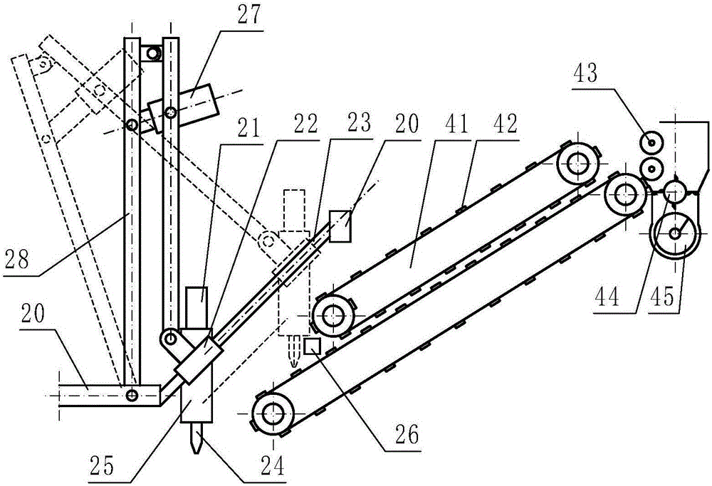
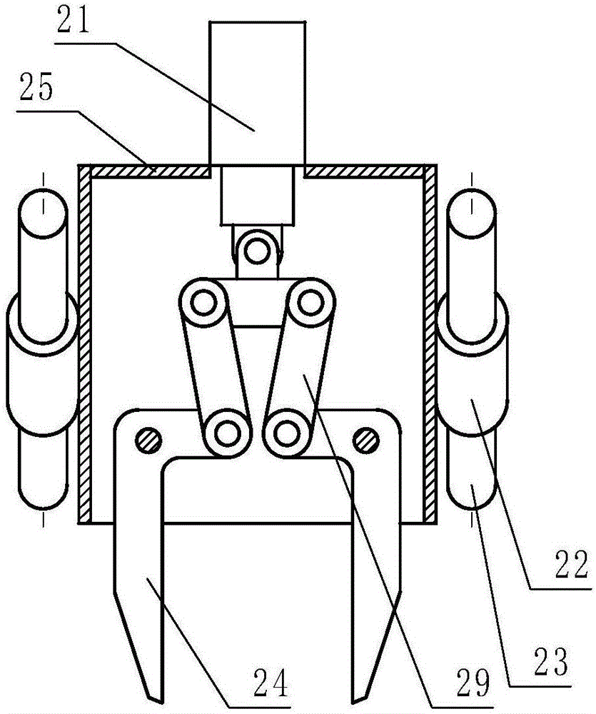
[0060] Embodiment 2: refer to Figure 15 , is a structural schematic diagram of Embodiment 2 of the present invention. Compared with Embodiment 1, the difference of this embodiment is that one end of the manipulator drive mechanism (21) is connected to the pick-up mechanism frame (20), and the other end is connected to the pick-up mechanism frame (20). The slide block (22) or the pick-up manipulator is connected, and the pick-up manipulator propulsion mechanism (27) pushes the pick-up manipulator to move along the pick-up guide rod (23).
Embodiment 3
[0061] Embodiment 3: refer to Figure 16 , is a structural schematic diagram of Embodiment 3 of the present invention. Compared with the previous embodiment, the difference of this embodiment is that the described pick-up guide rod (23) is a track provided with a chute, and the pick-up slide block (22) is The slide block in the chute can also move along the described pick-up guide rod (23).
PUM
 Abstract
Description
Claims
Application Information
 - R&D Engineer
- R&D Manager
- IP Professional
- Industry Leading Data Capabilities
- Powerful AI technology
- Patent DNA Extraction
Browse by: Latest US Patents, China's latest patents, Technical Efficacy Thesaurus, Application Domain, Technology Topic.
© 2024 PatSnap. All rights reserved.Legal|Privacy policy|Modern Slavery Act Transparency Statement|Sitemap