Drip irrigation belt pick-up mechanism and the automatic drip irrigation belt recovery machine constituted by it
A technology for picking up mechanisms and drip irrigation belts, applied to agricultural machinery and implements, harvesters, conveyor objects, etc., can solve problems such as low work efficiency, trouble, and low picking rate, and achieve the effect of reducing the degree of manual intervention
- Summary
- Abstract
- Description
- Claims
- Application Information
AI Technical Summary
Problems solved by technology
Method used
Image

Examples
Embodiment 1
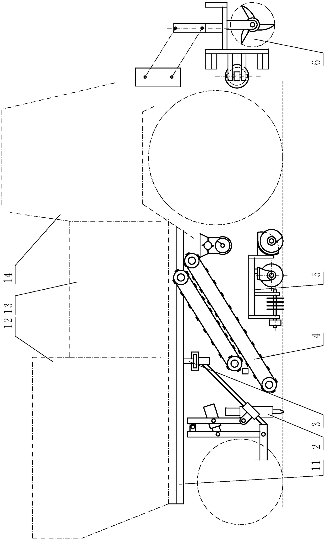
[0051] Embodiment 1: refer to Figure 1 to Figure 14 , the structural representation of the embodiment of the present invention 1 is a self-propelled full-automatic drip irrigation tape recovery machine, including power, main frame (11), transmission mechanism, drip irrigation tape collection mechanism (13), and is provided with on the main frame (11). A plurality of sets of drip irrigation tape picking mechanisms, the drip irrigation tape collection mechanism (13) is a combination of a drip irrigation tape crushing mechanism and a collection box.
[0052] The multiple groups of drip irrigation belt pick-up mechanisms are connected to the main frame (11) by suspension beams (31), the slide rails of the suspension beams (31), and the pick-up mechanism racks of more than two groups of drip irrigation belt pick-up mechanisms (20) be connected on the suspension crossbeam (31) by the slide block (32) that can move on described slide bar or slide rail, be provided with drip irrigati...
Embodiment 2
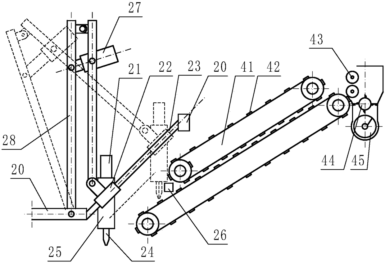
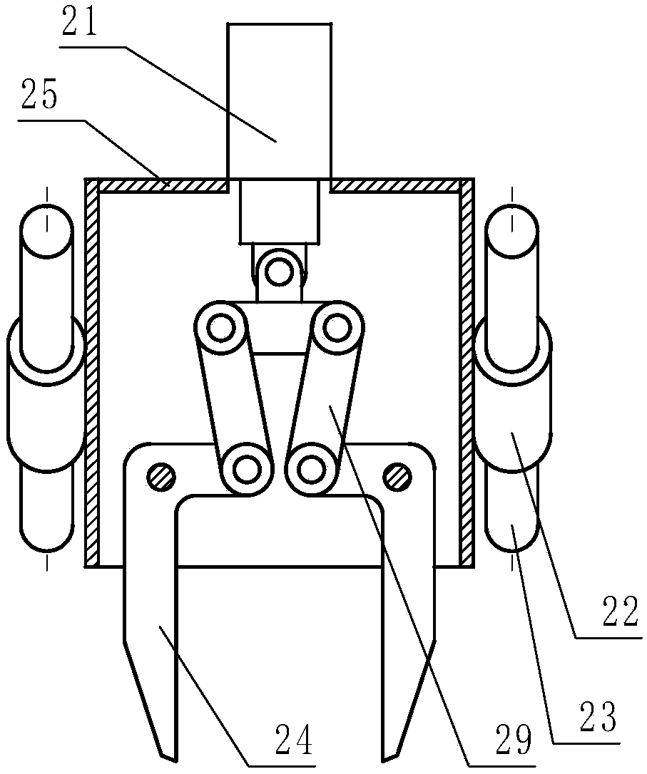
[0060] Embodiment 2: refer to Figure 15 , is a structural schematic diagram of Embodiment 2 of the present invention. Compared with Embodiment 1, the difference of this embodiment is that one end of the manipulator drive mechanism (21) is connected to the pick-up mechanism frame (20), and the other end is connected to the pick-up mechanism frame (20). The slide block (22) or the pick-up manipulator is connected, and the pick-up manipulator propulsion mechanism (27) pushes the pick-up manipulator to move along the pick-up guide rod (23).
Embodiment 3
[0061] Embodiment 3: refer to Figure 16 , is a structural schematic diagram of Embodiment 3 of the present invention. Compared with the previous embodiment, the difference of this embodiment is that the described pick-up guide rod (23) is a track provided with a chute, and the pick-up slide block (22) is The slide block in the chute can also move along the described pick-up guide rod (23).
PUM
 Abstract
Description
Claims
Application Information
 - R&D Engineer
- R&D Manager
- IP Professional
- Industry Leading Data Capabilities
- Powerful AI technology
- Patent DNA Extraction
Browse by: Latest US Patents, China's latest patents, Technical Efficacy Thesaurus, Application Domain, Technology Topic.
© 2024 PatSnap. All rights reserved.Legal|Privacy policy|Modern Slavery Act Transparency Statement|Sitemap