Full-automatic bulb replacement manipulator

A technology for changing light bulbs and manipulators. It is applied in the direction of manipulators, electrical components, manufacturing tools, etc. It can solve problems such as high installation position of light bulbs, electric shock of light bulbs, and inability to directly replace light bulbs.

Active Publication Date: 2017-01-18
SUZHOU RUIPENGCHENG SCI & TECH CO LTD
View PDF14 Cites 9 Cited by
  • Summary
  • Abstract
  • Description
  • Claims
  • Application Information

AI Technical Summary

Problems solved by technology

[0002] The installation position of the light bulb is high, and ordinary people cannot directly replace the light bulb
It is not suitable for the elderly or the infirm to replace the light bulb by climbing the ladder
In addition, there is a risk of electric shock if the bulb is replaced directly by hand.

Method used


Image

  • Full-automatic bulb replacement manipulator
  • Full-automatic bulb replacement manipulator

Examples


Embodiment Construction

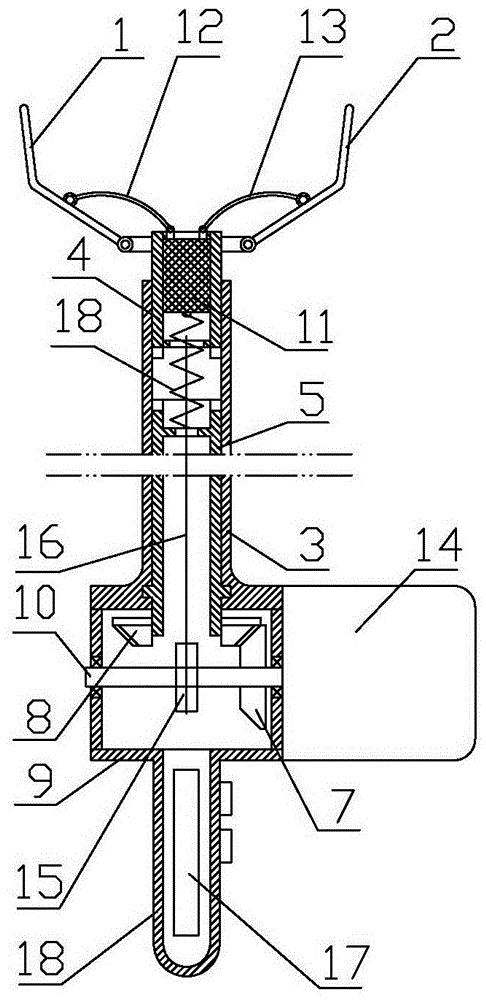
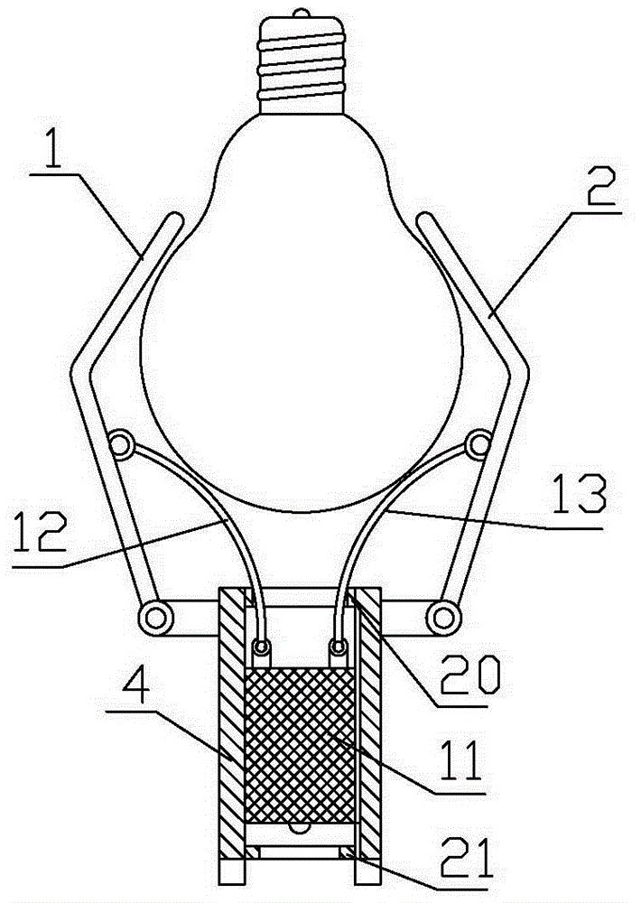
[0011] Such as figure 1 , figure 2 As shown, the fully automatic light bulb changing manipulator of the present invention includes a telescopic rod, a plurality of clamping claws 1 and 2 that are installed on the upper end of the telescopic rod and can be relatively contracted. That is, the light bulb that can reach a high place can hold the light bulb when the multiple clamping claws 1 and 2 shrink to complete the work of changing the light bulb. Just can hold spherical bulb, can also paste soft fabric layer on the inner side of clamping bar 1,2 in order to increase frictional force.

[0012] The telescopic rod includes an outer sleeve 3, an upper rod body 4, and a lower rod body 5, and the upper end of the outer sleeve 3 is hinged with the lower ends of the clamping claws 1, 2; the upper rod body 4 and the lower rod body 5 are all rotatably installed In the tubular structure in the inner cavity of the outer sleeve 3, the upper rod body 4 can rotate or move axially in the ...


PUM


Abstract

The invention relates to an electric manipulator, in particular to a full-automatic bulb replacement manipulator. The full-automatic bulb replacement manipulator comprises an extension rod and multiple clamping rods which are mounted at the upper end of the extension rod and can relatively extend and contract. The extension rod comprises an upper rod body and a lower rod body which are coaxially inserted together and are relatively rotatable. The clamping rods are mounted at the upper end of the upper rod body through hanging lugs. The middle segments of the clamping rods are connected with pull wires. A sliding block connected to the pull wires is arranged in an inner cavity of the upper rod body. The upper end of the lower rod body is connected with the upper rod body through a gear box. The upper rod body is connected with a drive motor in a transmission manner. A handle for driving the sliding block to move in the axial direction is mounted on the lower rod body. The manipulator is compact in structure, convenient to use and free of the risk of electric shock and the climbing requirement in use and solves the problems about bulb replacement by the aged.

Description

technical field [0001] The invention relates to an electric manipulator, in particular to a fully automatic light bulb changing manipulator. Background technique [0002] The installation position of the light bulb is high, and ordinary people cannot directly replace the light bulb. Use the way of ladder climbing high to replace light bulb and be unsuitable for the elderly or infirm again. In addition, there is a risk of electric shock if you replace the bulb directly by hand. These factors make changing the light bulb a headache in many families, and it is necessary to ask a special person to help change the light bulb. Contents of the invention [0003] The purpose of the present invention is to provide a fully automatic light bulb changing manipulator that does not have the risk of electric shock, does not need to climb high, and is easy to use. [0004] The technical scheme that the present invention adopts for solving technical problems is: [0005] The fully auto...

Claims


Application Information

Patent Timeline
Patent Type & Authority Applications(China)
IPC IPC(8): B25J1/00H01K3/32
CPCB25J1/00H01K3/32
Inventor 戴一畅
Owner SUZHOU RUIPENGCHENG SCI & TECH CO LTD
Why Eureka
Try Eureka