
A device for eliminating the blind area of ​​the A-pillar when the vehicle is turning

A blind spot and vehicle technology, applied in vehicle parts, signal devices, optical observation devices, etc., can solve problems such as driver's misjudgment and image distortion, and achieve the effects of improving safety, long service life and simple structure

Inactive Publication Date: 2019-02-05
ZHEJIANG JINGANG AUTOMOBILE +1
View PDF7 Cites 0 Cited by
  • Summary
  • Abstract
  • Description
  • Claims
  • Application Information

AI Technical Summary

Problems solved by technology

The disadvantage is that the image displayed by the convex mirror of the elimination device is distorted, which easily makes the driver make wrong judgments

Method used


Image

  • A device for eliminating the blind area of ​​the A-pillar when the vehicle is turning
  • A device for eliminating the blind area of ​​the A-pillar when the vehicle is turning

Examples


Embodiment

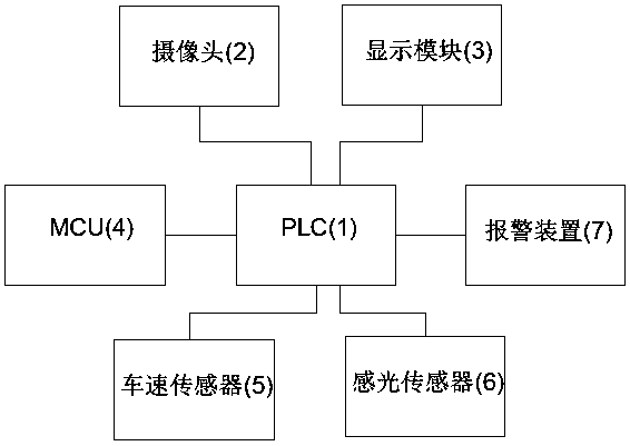
[0015] Embodiment: a circuit principle connection diagram, its structural diagram is as follows figure 1 As shown, it includes PLC1, camera 2 and display module 3. The PLC is electrically connected to the camera and the display module at the same time. The cameras are respectively arranged on the left and right rear-view mirror housings of the car, and the display modules are respectively arranged on the left A-pillar of the car. on the trim panel and on the right A-pillar trim panel. The PLC is also electrically connected with the car MCU4. The PLC is also electrically connected to the vehicle speed sensor 5 and the photosensitive sensor 6 . The device for eliminating the blind area of ​​the A-column when the vehicle is turning also includes an alarm device 7, which is connected to the PLC.

[0016] The camera is used to shoot the blind spots of the left A-pillar and the right A-pillar of the car. The camera information of the camera on the left rearview mirror of the car i...


PUM


Abstract

The invention discloses a device for eliminating a column A blind zone during vehicle steering. The device comprises a PLC, cameras and display modules, wherein the PLC is electrically connected with the cameras and the display modules simultaneously; the cameras are respectively arranged on the left and right rearview mirror housings of a vehicle; the display modules are respectively arranged on the left and right column A decorative boards of the vehicle. The device for eliminating the column-A blind zone during vehicle steering can effectively eliminate a vision blind zone generated by a column A of the vehicle; when the vehicle steers, and a driver forgets to open a steering lamp, the device can remind the driver of opening the steering lamp or automatically open the steering lamp.

Description

technical field [0001] The invention relates to the technical field of automobile safety, in particular to a device for eliminating the blind area of ​​an A-column when a vehicle is turning. Background technique [0002] The A-pillar is above the left and right rear-view mirrors between the engine compartment and the cockpit, which will block a part of the turning field of view, that is, the blind spot of vision. The angle of the driver's line of sight will always be more or less blocked. Under normal circumstances, when the driver passes the line of sight at the A-pillar, the binocular overlap angle is 5~6 degrees. If the driver's comfortable angle is considered, the smaller the overlap angle, the better, and the thinner the A-pillar, the better, but at the same time One problem is the safety of the vehicle. Obviously, we must ensure the high rigidity of the A-pillar to reduce the risk of safety. Otherwise, while reducing the blind spot of the field of vision, it will bring...

Claims


Application Information

Patent Timeline
Patent Type & Authority Patents(China)
IPC IPC(8): B60R1/00B60Q1/34
CPCB60Q1/346B60R1/00B60R2300/105B60R2300/202
Inventor 李书涛倪三明张吉
Owner ZHEJIANG JINGANG AUTOMOBILE
Learn More