Unmanned aerial vehicle based continuous dropping device and controller

A technology of unmanned aerial vehicles and driving devices, which is applied in the direction of unmanned aerial vehicles, launching devices, aircrafts, etc., and can solve the problems that unmanned aerial vehicles cannot achieve continuous throwing

Active Publication Date: 2017-01-18
SIASUN CO LTD
View PDF6 Cites 12 Cited by
  • Summary
  • Abstract
  • Description
  • Claims
  • Application Information

AI Technical Summary

Problems solved by technology

[0003] The purpose of the present invention is to propose a UAV continuous throwing device and controller to solve the technical problem that UAVs in the prior art cannot achieve continuous throwing

Method used


Image

  • Unmanned aerial vehicle based continuous dropping device and controller
  • Unmanned aerial vehicle based continuous dropping device and controller
  • Unmanned aerial vehicle based continuous dropping device and controller

Examples


Embodiment 1

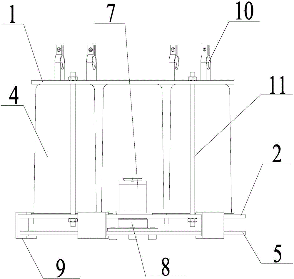
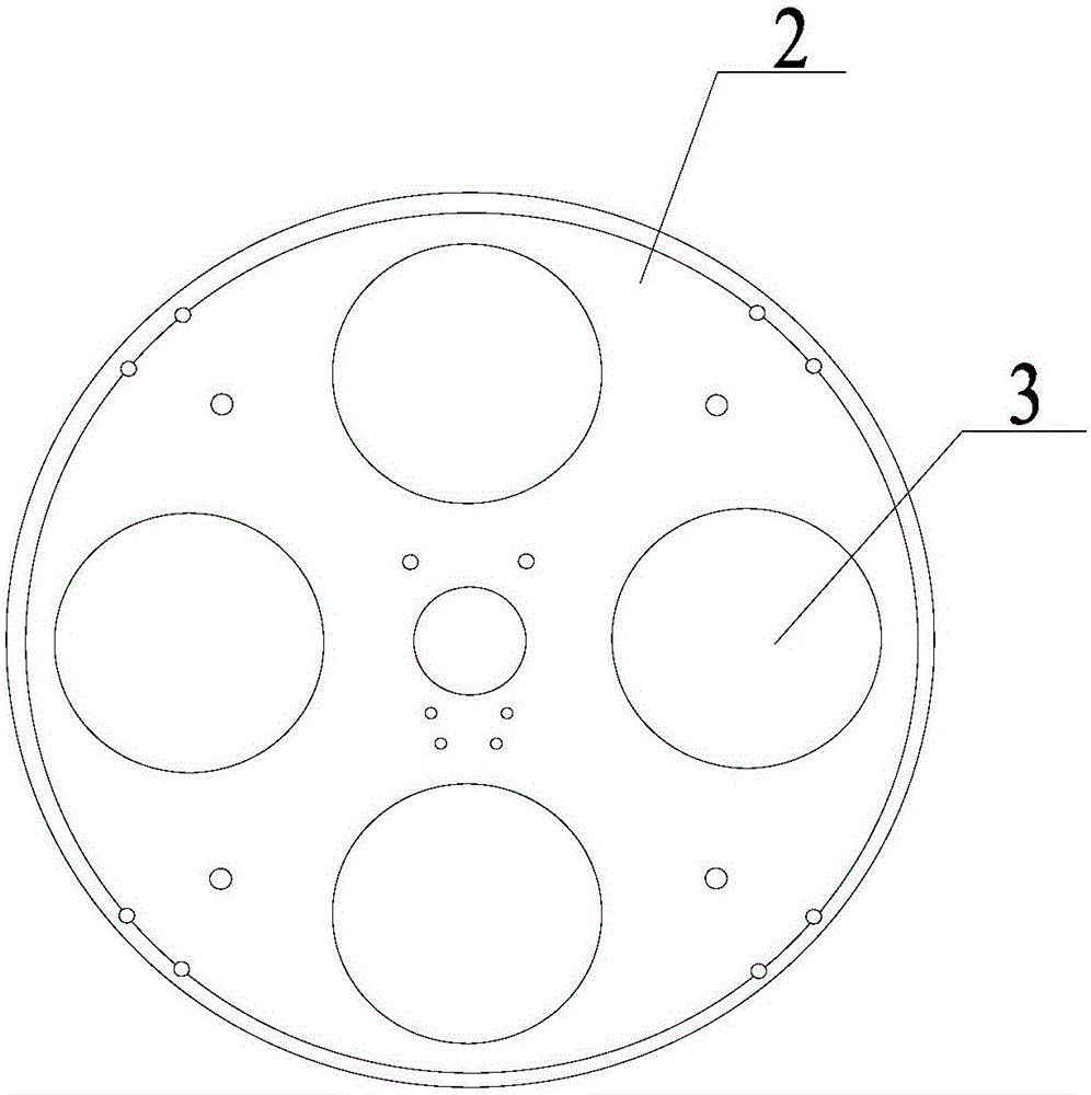
[0026] Such as Figure 1-3 As shown, a continuous throwing device for unmanned aerial vehicle comprises an upper splint 1 and a lower splint 2, the upper splint 1 and the lower splint 2 are fixedly connected, the lower splint 2 is provided with a plurality of through holes 3, and the plurality of through holes 3 are in the form of Circumferentially distributed, a plurality of storage containers 4 are arranged between the upper splint 1 and the lower splint 2, and the bottom of the storage container 4 is provided with an opening, and the opening is arranged opposite to the through hole 3;

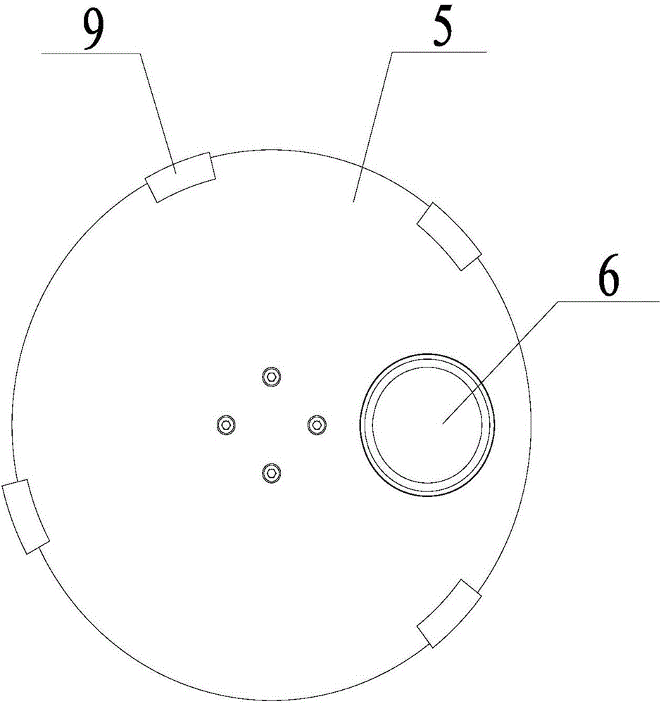
[0027] The side of the lower splint 2 away from the upper splint 1 is provided with a rotating plate 5, the rotating plate 5 is parallel to the lower splint 2, and a leakage hole 6 is provided on the rotating plate 5, the leakage hole 6 is not smaller than the through hole 3, and the rotating plate 5 is parallel to the lower splint 2. 5 is connected with a driving device, the driving device ...

Embodiment 2

[0040] A controller for an unmanned aerial vehicle continuous throwing device, including a remote control end and a receiving end, the remote control end includes a control button, the control button is connected to a first processor, and the first processor is connected to a transmitting module;

[0041] The receiving end includes a receiving module, the receiving module is connected with a second processor, and the second processor is connected with the steering gear 7 of the UAV continuous throwing device in Embodiment 1.

[0042] Preferably, the first processor and the second processor are STC15W408AS single-chip microcomputers. The transmitting module is a 2.4G radio frequency module.

[0043] During specific use, the continuous throwing device is connected with the frame of the unmanned aerial vehicle by the connector 10, and the object to be thrown is placed in the storage container 4. After the unmanned aerial vehicle takes off, the flight track and the When the parab...


PUM


Abstract

The invention relates to the technical field of unmanned aerial vehicle based dropping equipment, and in particular to an unmanned aerial vehicle based continuous dropping device and a controller. The device comprises an upper clamping plate and a lower clamping plate. A plurality of through holes are formed in the lower clamping plate. A plurality of storage containers are disposed between the upper clamping plate and the lower clamping plate. An opening is formed in a bottom end of each storage container, and all the openings are opposed to the through holes. A rotating plate is disposed at one side, far away from the upper clamping plate, of the lower clamping plate, and a leaking hole is formed in the rotating plate. The rotating plate is connected to a driving device. The driving device comprises a steering engine that is connected to a rotating shaft. The rotating shaft is connected to the rotating plate. The unmanned aerial vehicle based continuous dropping device and the controller provided by the present invention may achieve continuous dropping by controlling the rotation of the rotating plate with the steering engine; articles for dropping are loaded in the storage containers; and the rotation angle of the steering engine may be accurately controlled by means of a PWM wave duty ratio.

Description

technical field [0001] The invention relates to the technical field of drone throwing equipment, in particular to a drone continuous throwing device and a controller. Background technique [0002] With the rapid development of drone technology and the maturity of the market, drones have been widely used in society. However, there are very few technologies and products for using drones to drop objects in the air. Continuous throwing cannot be achieved, and the flying safety of the UAV is affected during the throwing process. Contents of the invention [0003] The purpose of the present invention is to propose a continuous throwing device and a controller for unmanned aerial vehicles to solve the technical problem in the prior art that the unmanned aerial vehicle cannot realize continuous throwing. [0004] For reaching this purpose, the present invention adopts following technical scheme: [0005] A continuous throwing device for an unmanned aerial vehicle, comprising an...

Claims


Application Information

Patent Timeline
Patent Type & Authority Applications(China)
IPC IPC(8): B64D1/02
CPCB64D1/02B64U10/10
Inventor 李双于淼江林斌杨跞
Owner SIASUN CO LTD
Why Eureka
Try Eureka