Tarpaulin open-top container

A container and tarpaulin technology, applied in the field of containers, can solve problems such as structural operation troubles, waste of manpower, water leakage, etc.

Active Publication Date: 2017-01-18
NANTONG CIMC SPECIAL TRANSPORTATION EQUIP MFR +2
View PDF9 Cites 2 Cited by
  • Summary
  • Abstract
  • Description
  • Claims
  • Application Information

AI Technical Summary

Problems solved by technology

[0002] The existing open-top container has an opening at the top. In order to prevent rainwater from entering the box, a tarpaulin is arranged on the top. The rope loop passed through can realize the fixing and watertightness of the tarpaulin; but the operation of this structure is more troublesome and wastes a lot of manpower
[0003] At present, there is also a sliding top-type tarpaulin open top box. A top bow is fixed under the tarpaulin, and the top

Method used


Image

  • Tarpaulin open-top container
  • Tarpaulin open-top container
  • Tarpaulin open-top container

Examples


no. 1 approach

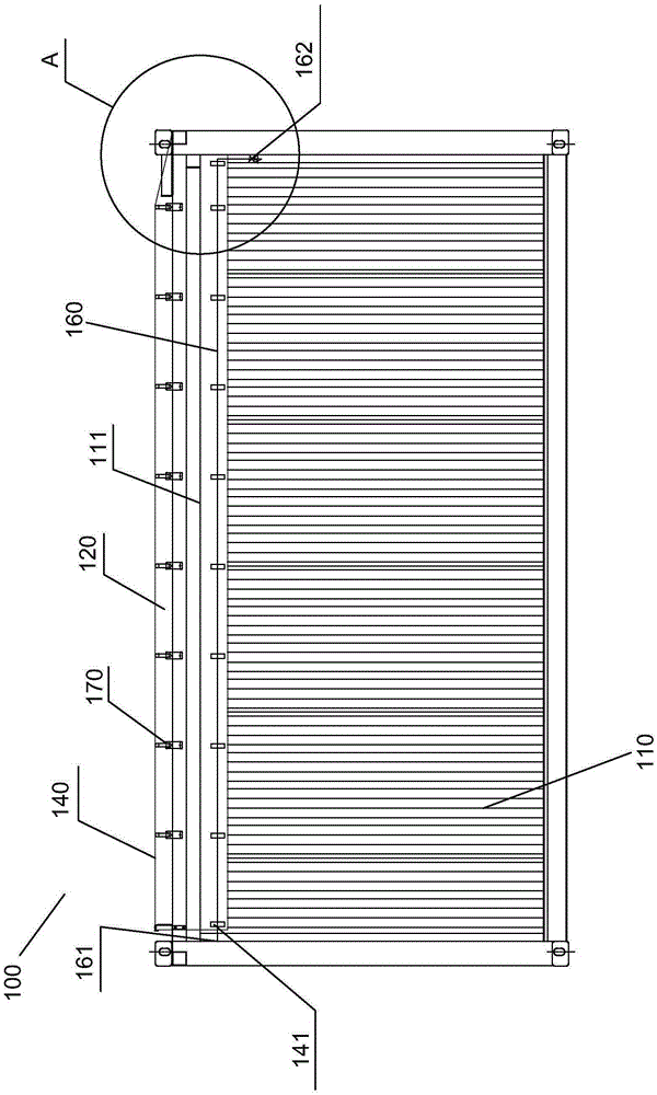
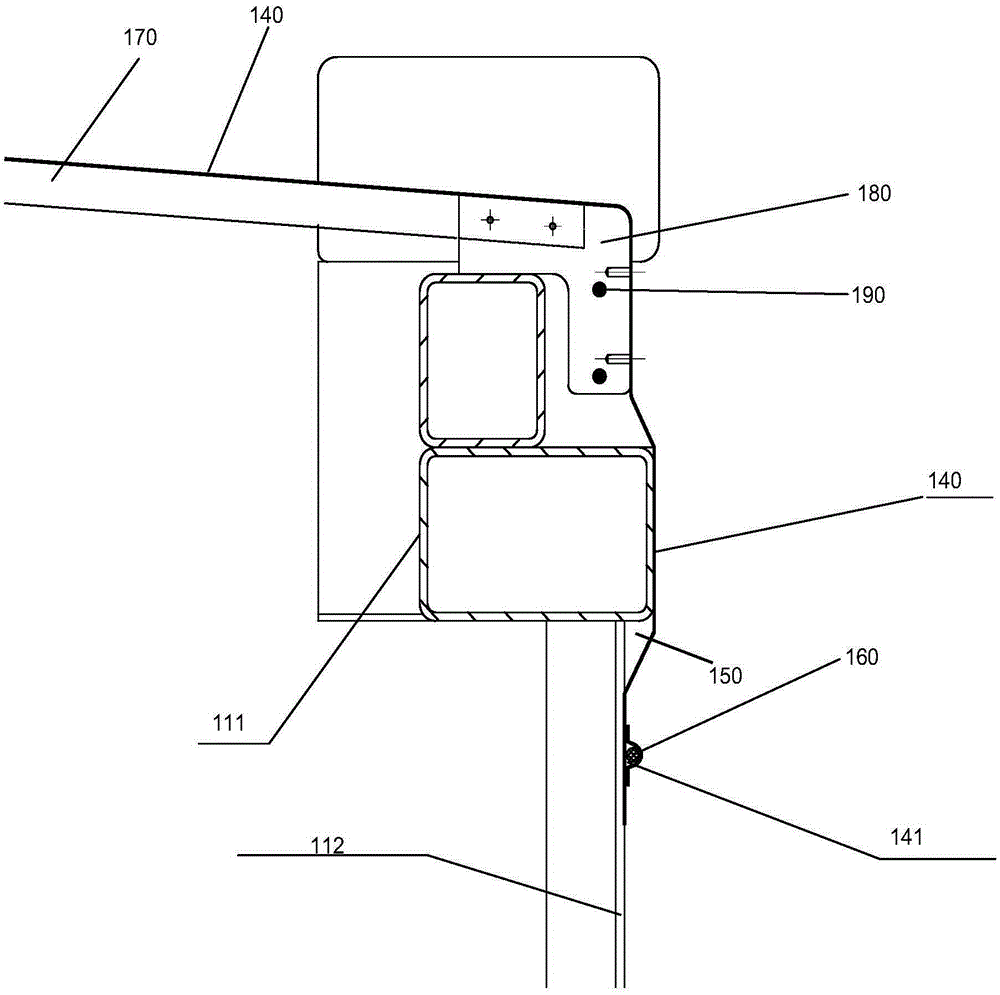
[0046] Figure 1-Figure 2 The first embodiment of the tarpaulin open top container of the present invention is schematically shown.

[0047] The box body 110 of the tarpaulin open-top container 100 includes a top side beam 111 extending longitudinally along the box body. The top side beam 111 is located at the top 130 of the box body 110. The top side beam in the present invention is the end beam at the top, which can be is the top side, or it can be the top face. The top 130 of the case has an opening 120 . The top of the box is provided with at least one (eg 5-20) top bows 170 extending laterally along the box, and the top bows 170 are arranged roughly parallel to the end surface of the box. Both ends of the top bow 170 are provided with sliders 180 , and the sliders 180 are arranged on the top side beams and can slide relative to the top side beams 111 along the longitudinal direction of the box body. The slider 180 may be provided with holes or depressions, and these ho...

no. 2 approach

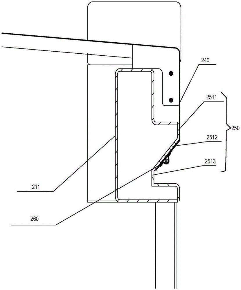
[0053] In this embodiment, for the sake of brevity, descriptions of the same parts as those in the first embodiment are omitted here. In this second embodiment, the reference numerals of the components corresponding to the first embodiment are the same, except that the first digit is changed from "1" to "2". This embodiment differs from the first embodiment in that, as image 3 As shown, a stepped portion 250 is formed on the outer wall of the top side beam 211 , and the stepped portion 250 can be formed by pressing the top side beam 211 . The stepped portion 250 includes a first extension 2511 , a second extension 2512 and a third extension 2513 , the first extension 2511 is the outer surface of the top side beam and extends downwards, the second extension 2512 extends from the first extension 2511 The bottom end of the second extension portion 2512 extends downwards from the bottom end of the second extension portion 2512 . The included angle between the first extension pa...

no. 3 approach

[0055] In this embodiment, for the sake of brevity, descriptions of the same parts as those in the second embodiment are omitted here. In this third embodiment, the reference numerals of the components corresponding to the second embodiment are the same, except that the first digit is changed from "2" to "3". This embodiment differs from the second embodiment in that, as Figure 4 As shown, the included angle between the first extension part 3511 and the second extension part 3512 is 90 degrees, the first end of the sealing rope 360 ​​can be arranged on the third extension part 3513 through bolt connection, and the second end of the sealing rope 360 It can be tightened to the other end of the third extension part 3513 , so that when the second end of the sealing rope 360 ​​is tightened, the sealing rope 360 ​​drives the tarpaulin 340 to be pressed against the first extension part 3511 and the third extension part 3513 . The structure is easy to process and facilitates the for...


PUM

PropertyMeasurementUnit
Angleaaaaaaaaaa

Abstract

The invention discloses a tarpaulin open-top container. The tarpaulin open-top container comprises a container body; a top side beam, an opening and a tarpaulin are arranged at the top of the container body; a hole is formed in at least one side edge of the tarpaulin; a sealing rope passes through the hole; the sealing rope comprises a first end and a second end; a step part is arranged at least one outer side of the top of the container body; when the tarpaulin is located in an extension state, the side edge, with the hole, of the tarpaulin can cover the step part; and the container body is constructed to ensure that the second end of the sealing rope can be tightened or loosened relative to the container body. According to the tarpaulin open-top container disclosed by the invention, the sealing rope tightly stretches to press the edge of the tarpaulin, and the tarpaulin is convenient to operate, so that the production cost is greatly reduced, the efficiency is enhanced and convenience is brought to water tightness.

Description

technical field [0001] The invention relates to the field of containers, in particular to a tarpaulin open-top container. Background technique [0002] The existing open-top container has an opening at the top. In order to prevent rainwater from entering the box, a tarpaulin is arranged on the top. The fixed and watertight tarpaulin can be realized through the looped rope; however, the operation of this structure is troublesome and wastes a lot of manpower. [0003] At present, there is also a sliding top-type tarpaulin open top box. A top bow is fixed under the tarpaulin, and the top bow can slide on the top side beam to realize the opening of the tarpaulin. For example, patent applications WO2004052754A1 and CN201080067790.5 A kind of tarpaulin sliding type open top box, but in this structure, there is a large gap between the top bow, between the tarpaulin and the top side beam, making it difficult to achieve sealing between the tarpaulin and the box body. When the wind ...

Claims


Application Information

Patent Timeline
IPC IPC(8): B65D88/12B65D90/00
CPCB65D88/12B65D90/00
Inventor 董春健陆新林黄志军郭晓生李爱华
Owner NANTONG CIMC SPECIAL TRANSPORTATION EQUIP MFR
Why Eureka
Try Eureka