Axial elastic gear and flexible joint mechanism

A technology of flexible joints and elastic gears, applied in the direction of gear transmission, belt/chain/gear, mechanical equipment, etc., can solve problems such as restricting the flexibility of the driven shaft and affecting the normal operation of machinery

Active Publication Date: 2017-01-18
孙长顺
View PDF6 Cites 2 Cited by
  • Summary
  • Abstract
  • Description
  • Claims
  • Application Information

AI Technical Summary

Problems solved by technology

[0004] At present, the common gear transmission methods of machinery or mechanisms are mostly rigid butt joint meshing input, requiring the two axes to be parallel, otherwise linear thrust other than normal meshing and push

Method used


Image

  • Axial elastic gear and flexible joint mechanism

Examples


Embodiment Construction

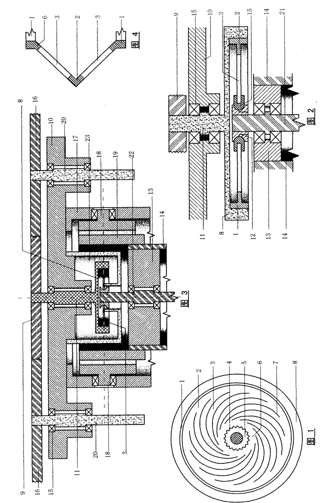
[0026] Select the mechanism shown in Figure 2, and press the disc with the teeth shown in Figure 1.

[0027] 1. Making disc teeth

[0028] 1. Make a disc:

[0029] a. Select a spring steel plate and cut it into 2 rings;

[0030] b. Cut the middle of the ring into the involute or other arc type shown in Figure 1 by means of laser cutting, etc., and divide the middle into several spiral spokes;

[0031] c. Cut the inner holes of the two rings into inner teeth (round-head core teeth are not used in this example).

[0032] 2. Production of dish teeth:

[0033] a. First make a rigid ring with an inner diameter equal to the outer diameter of the disc, as a mounting rib for the disc teeth;

[0034] b. Stack and fix the two discs according to the spiral direction of the involute, one reverse and one forward, and leave a certain gap between the two discs so that the axial elastic deformation capabilities of the two discs do not affect each other;

[0035] c. Fix the stacked and fi...


PUM


Abstract

The invention relates to an axial elastic dish gear and a flexible power input joint mechanism thereof. The mechanism mainly comprises a power source, a machine frame, a gear shaft, a special gear, a transitional sleeve disk, a dome inner gear, a dish gear bracket and the like; the joint mainly comprises the dish gear, a sleeve disk and a worm wheel type rigid gear; the dish gear of the joint is an axial elastic gear and mainly comprises a mounting rib, inner and outer buffer rib plates, a spoke and the inner gear; and the flexible joint formed by the dish gear can transfer the power of a power shaft to a driven shaft in a variable direction.

Description

[0001] technology type [0002] The present invention relates to a mechanical component and mechanism, the flexible joints of which are mainly constructed of axially elastic gears. [0003] technical background [0004] At present, the common gear transmission methods of machinery or mechanisms are mostly rigid butt joint meshing input, requiring the two axes to be parallel, otherwise linear thrust other than normal meshing and pushing will be generated between the two axes, making the driven shaft and related The torsional displacement of the mechanism affects the normal operation of the machine and also restricts the flexibility of the driven shaft. Contents of the invention [0005] The axial elastic gear and flexible joint mechanism is realized by changing the stiffness of the web between the dedendum circle and the shaft hole of one of the gears and enhancing its local radial elasticity on the basis of the meshing of the rigid gears. No mechanism can effectively elimina...

Claims


Application Information

Patent Timeline
IPC IPC(8): F16H55/14F16H55/17F16H1/20
CPCF16H1/20F16H55/14F16H55/17
Inventor 孙长顺
Owner 孙长顺
Why Eureka
Try Eureka