usb control circuit with built-in signal relay circuit

A technology of signal relay and control circuit, applied in electrical digital data processing, climate sustainability, instruments, etc., can solve the problems of normal data transmission, limitation, and use of USB host devices and USB peripheral devices

Active Publication Date: 2019-05-07
REALTEK SEMICON CORP
View PDF6 Cites 0 Cited by
  • Summary
  • Abstract
  • Description
  • Claims
  • Application Information

AI Technical Summary

Problems solved by technology

[0004] However, the connection objects of the uplink port and the downlink port of the traditional USB hub device cannot be swapped, otherwise it will lead to the problem that normal data transmission cannot be performed between the USB master device and the USB peripheral device
For example, when an OTG device is connected to the uplink port of a traditional USB hub device, it can only be used as a USB master device, but cannot be used as a USB peripheral device
On the other hand, when an OTG device is connected to the downstream connection port of a traditional USB hub device, it can only be used as a USB peripheral device and cannot be used as a USB master device.
[0005] Therefore, when two OTG devices are respectively connected to the upstream connection port and the downstream connection port of the traditional USB hub device, the roles played by these two OTG devices are limited and cannot be reversed.
[0006] Obviously, the structure of the traditional USB hub device limits the use of the OTG device, and it cannot be switched according to actual needs to adapt to the role of the OTG device.

Method used


Image

  • usb control circuit with built-in signal relay circuit
  • usb control circuit with built-in signal relay circuit
  • usb control circuit with built-in signal relay circuit

Examples


Embodiment Construction

[0039] Embodiments of the present invention will be described below in conjunction with related drawings. In the drawings, the same reference numerals represent the same or similar elements or method flows.

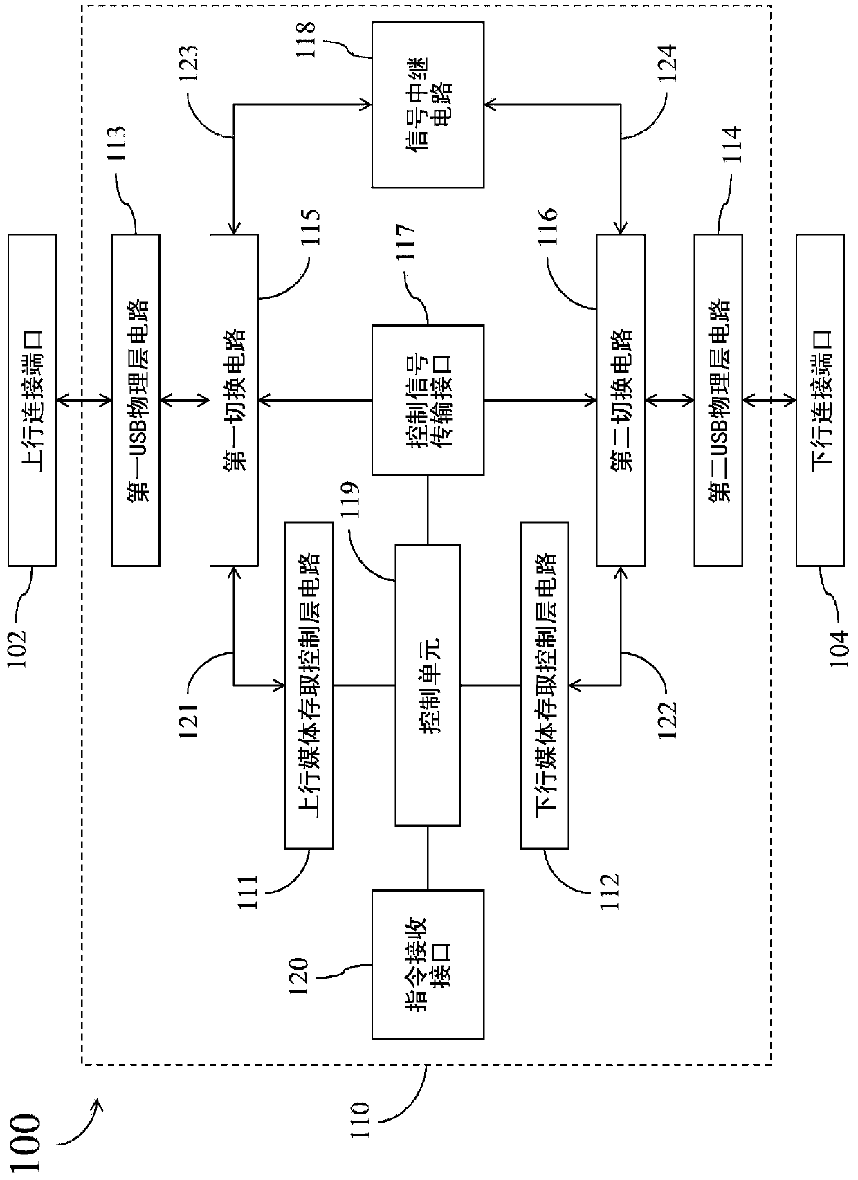
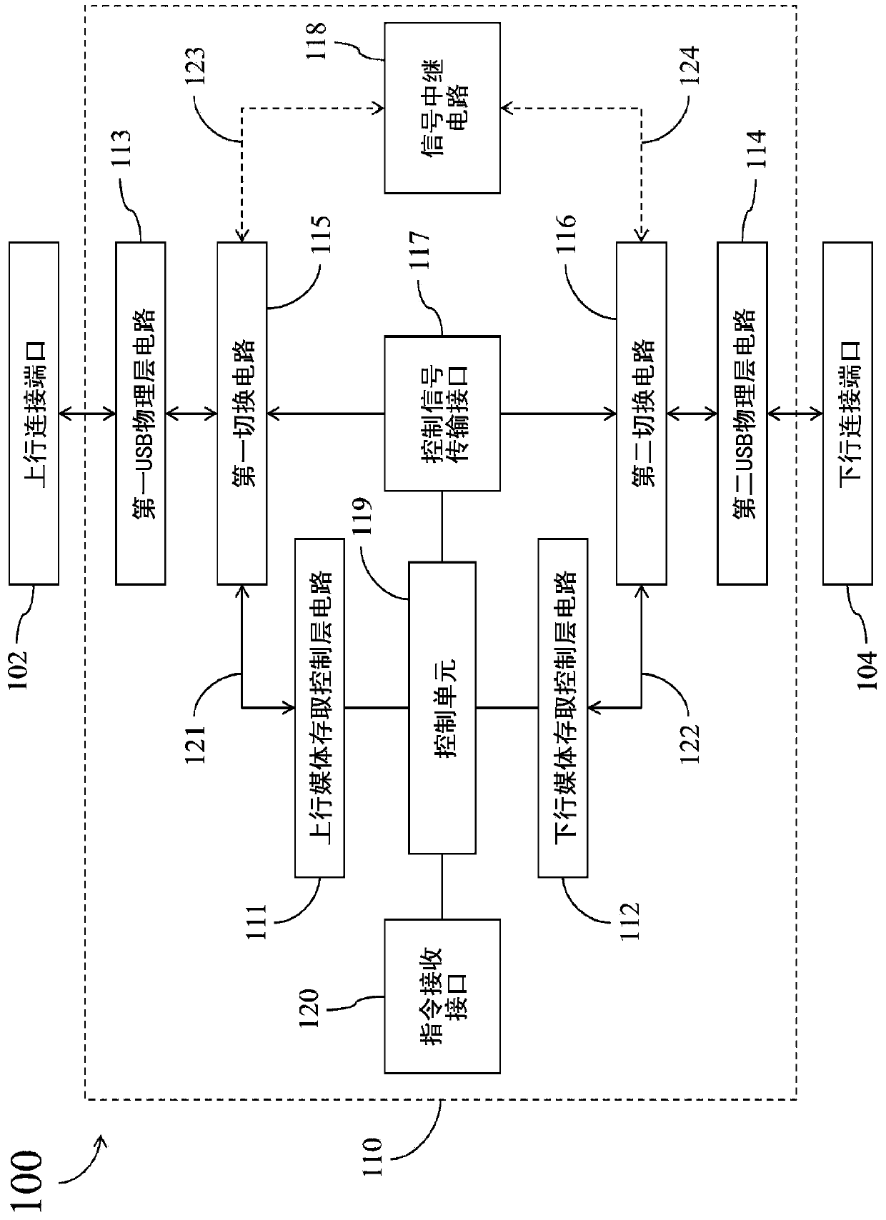
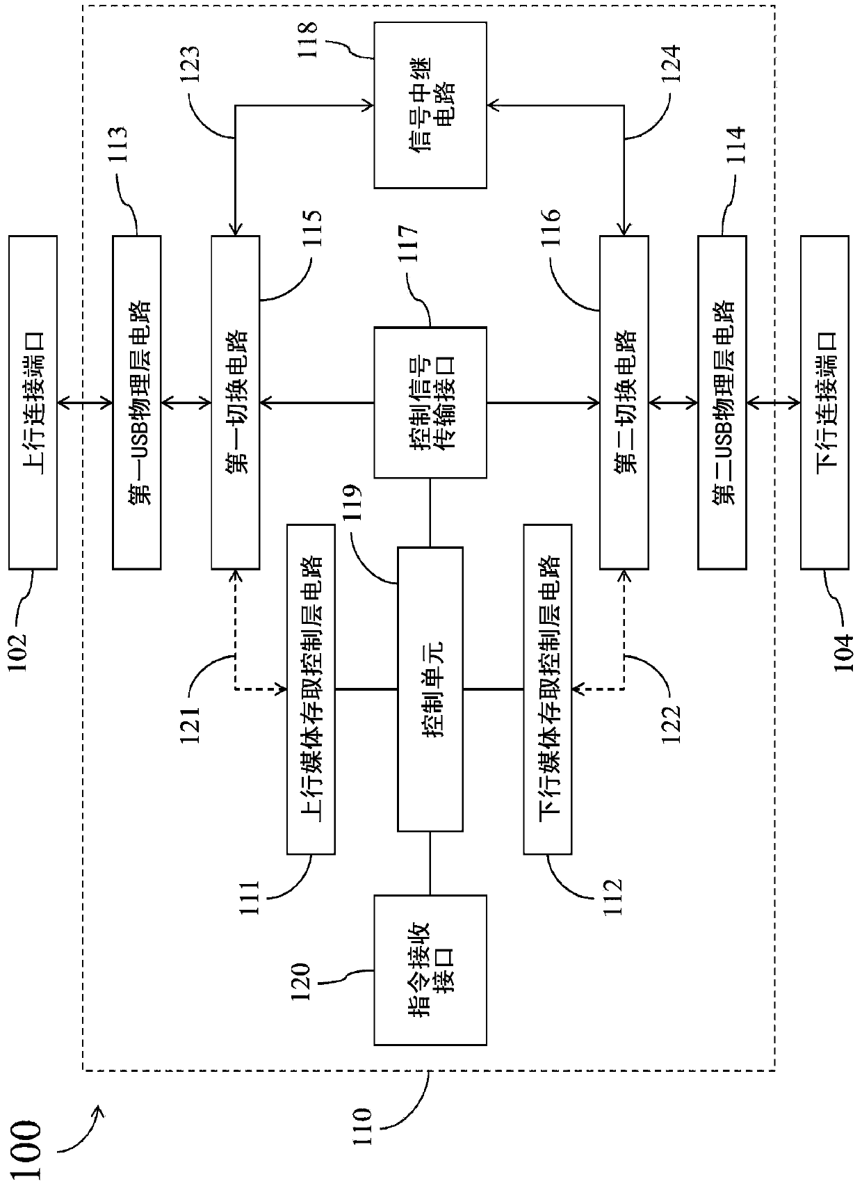
[0040] figure 1 It is a simplified functional block diagram of the USB hub device 100 according to an embodiment of the present invention. The USB hub device 100 includes an uplink port 102 , a downlink port 104 , and a USB control circuit (USB control circuit) 110 . exist figure 1 In the embodiment of the present invention, the USB control circuit 110 includes: an upstream media access control layer circuit (upstream MAC-layer circuit) 111, a downstream media access control layer circuit (downstream MAC-layer circuit) 112, a first USB physical layer circuit (USB PHY-layer circuit) 113, a second USB physical layer circuit 114, a first switching circuit (switch circuit) 115, a second switching circuit 116, a control signal transmission interface (control signal transmis...


PUM


Abstract

A USB control circuit of a USB hub device includes: an upstream MAC-layer circuit; a downstream MAC-layer circuit; a first USB PHY-layer circuit; a second USB PHY-layer circuit; a first switch circuit for communicating data with an upstream port through the first USB PHY-layer circuit; a second switch circuit for communicating data with a downstream port through the second USB PHY-layer circuit; a control signal transmission interface; a signal repeater circuit; and a control unit configured to operably control the first switch circuit and the second switch circuit through the control signal transmission interface, so that the first switch circuit selectively couples the upstream MAC-layer circuit or the signal repeater circuit with the first USB PHY-layer circuit, while the second switch circuit selectively couples the downstream MAC-layer circuit or the signal repeater circuit with the second USB PHY-layer circuit.

Description

technical field [0001] The invention relates to a USB control circuit, especially a USB control circuit with a built-in signal relay circuit. Background technique [0002] A USB hub device is a very common data transmission device, and its main function is to convert and distribute data between a USB host device (USB host device) and a USB peripheral device (USB peripheral device). The USB hub device includes an upstream port for connecting to a USB host device, and a downstream port for connecting to a USB peripheral device. [0003] The OTG (On-the-Go) function is defined in the supplementary specification of the USB protocol, which allows USB peripheral devices (also known as OTG devices) that support OTG functions to selectively play the role of USB master devices or The role of USB peripherals. Therefore, the OTG device is classified as a dual role device. [0004] However, the connection objects of the uplink port and the downlink port of the traditional USB hub dev...

Claims


Application Information

Patent Timeline
Patent Type & Authority Patents(China)
IPC IPC(8): G06F13/38G06F13/40
CPCG06F13/385G06F13/4045G06F13/4022G06F13/4282Y02D10/00
Inventor 刘冲王骆宾曾建中林能贤
Owner REALTEK SEMICON CORP
Why Eureka
Try Eureka