Pulse field enrichment ion migration tube

A technology of ion transfer tube and pulse field, which is applied in the field of pulse field enrichment ion transfer tube, can solve the problems of electric field distortion, increase the cutting width of ion gate, etc., and achieve the effect of improving sensitivity

Inactive Publication Date: 2017-01-18
DALIAN INST OF CHEM PHYSICS CHINESE ACAD OF SCI
View PDF3 Cites 6 Cited by
  • Summary
  • Abstract
  • Description
  • Claims
  • Application Information

AI Technical Summary

Benefits of technology

This technology improves how well it works when analyzing molecules that move through an electric field compared with other methods like mass spectrometry or liquid chromatography. It allows us to measure very small quantities quickly while maintaining high accuracy.

Problems solved by technology

The technical problem addressed in this patents relates to improving the accuracy or sensitivity of detectors made up of multiple components such as an electron gate, which are commonly found in mass analysis instruments like IMS. While these devices work well at high temperatures but they may also suffer low detection efficiencies due to their use of electrons. To address this issue, there exist techniques called electronic nose technology, where specific parts of the device help identify charged particles more accurately while reducing noise levels.

Method used


Image

  • Pulse field enrichment ion migration tube
  • Pulse field enrichment ion migration tube

Examples


Embodiment 1

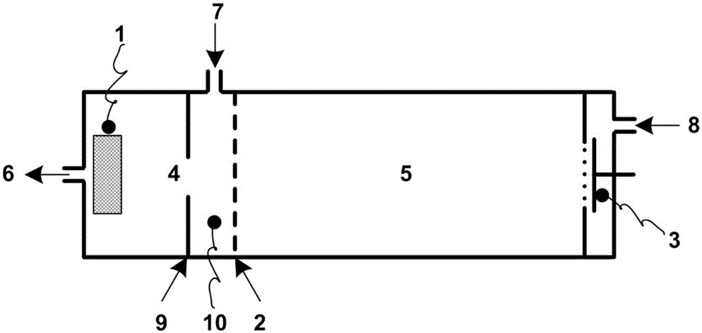
[0031] like figure 1 As shown, a pulsed field enrichment ion transfer tube is a hollow cylindrical cavity, and a columnar reactive ion generating device ion source 1 and a columnar ion receiving device Faraday disk 3 are respectively arranged at both ends of the cavity; A Bradbury-Nielsen ion gate 2 is set between the ion source and the Faraday disk, and the inner part of the chamber is divided into two regions, wherein a reaction zone 4 is formed between the ion source and the ion gate, and a migration zone 5 is formed between the ion gate and the Faraday disk; The feature is that an annular pulse electrode 9 is arranged inside the reaction area, the pulse electrode is parallel to the ion gate, and a pulse field ion enrichment area 10 is formed between the pulse electrode and the ion gate.

[0032] The ion source, pulse electrode, ion gate and farad chassis are coaxially arranged in the ion transfer tube;

[0033] The ion gate is composed of a grid-shaped first gate electrod...


PUM


Abstract

The invention relates to a pulse field enrichment ion migration tube. The pulse field enrichment ion migration tube is characterized in that high-voltage pulse, which is synchronized to ion gate open pulse, is applied to a pulse electrode set between an ion source and an ion gate, the movement speed of ions is greatly improved during a period of opening the ion gate, and more ions are enabled to pass the ion gate; and meanwhile, spatial focusing is carried out on an ion cluster passed the ion gate by using the difference, which is caused by the high-voltage pulse, in electric field intensity at two sides of the ion gate, and the original resolution of the iron migration tube is maintained.

Description


Claims


Application Information

Patent Timeline
Owner DALIAN INST OF CHEM PHYSICS CHINESE ACAD OF SCI
Why Eureka
Try Eureka