Glue spraying device for shoemaking

A technology for spraying glue and shoes, applied in the direction of spraying device, etc., can solve problems such as time-consuming and inconvenient operation, and achieve the effect of saving cost, saving time and manpower, and overcoming time-consuming and inconvenient operation.

Inactive Publication Date: 2017-01-25
成都卡美奇鞋业有限公司
View PDF5 Cites 2 Cited by
  • Summary
  • Abstract
  • Description
  • Claims
  • Application Information

AI Technical Summary

Problems solved by technology

[0002] In the shoe-making process, the bonding between the sole and the upper is often done by gluing, which requires spraying glue on the sole. The existing glue spraying device often uses a syringe to install the glue spraying port, which requires manual control of reciprocating operations. It takes a lot of time to complete the glue spraying work at the glue spray port, and it is inconvenient to operate. Therefore, it is necessary to design a glue spraying device for shoemaking that can spray glue quickly and is easy to operate.

Method used


Image

  • Glue spraying device for shoemaking

Examples


Embodiment 1

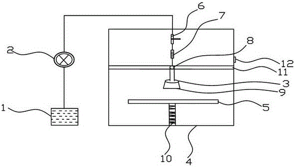
[0017] Such as figure 1 As shown, a glue spraying device for shoemaking provided by the present invention includes a liquid storage tank 1, a liquid pumping device 2, an operation box 4, a glue spray port 3 and a placement table 5, and the glue spray port 3 and the placement table 5 are placed In the operation box 4, the glue spray port 3 is located directly above the placement table 5, the liquid storage tank 1, the liquid pumping device 2 and the glue spray port 3 are connected in sequence through the infusion pipeline, the glue spray port 3 is a circular closed structure, and the circular closed There are a number of leakage holes on the structure, the circular closed structure is covered with a glue spray cover 9, a flow regulating valve 6 is arranged between the liquid pumping device 2 and the circular closed structure, a sliding rod 11 is arranged on the operation box 4, and a sliding rod 11 is installed on the sliding rod 11. Electric pulley 8, circular closed structure...

Embodiment 2

[0020] Based on Example 1, such as figure 1 As shown, the above-mentioned placing platform 5 is provided with a miniature hydraulic lift 10, and the miniature hydraulic lift 10 is fixed on the bottom of the operation box 4.

[0021] The miniature hydraulic lifter 10 can lower the placement table to a height suitable for the user to place the sample to be sprayed, which is convenient for the user to operate.

Embodiment 3

[0023] Based on Example 1, such as figure 1 As shown, a flow meter 7 is arranged between the above-mentioned flow regulating valve 6 and the circular closed structure.

[0024] The flow meter 7 is convenient for the user to read the flow rate of the glue, and it is convenient for the user to cooperate with the flow regulating valve 6 to control the amount of the glue, so that the glue can be used rationally to save costs.


PUM


Abstract

The invention discloses a glue spraying device for shoemaking, which includes a liquid storage tank, a liquid pumping device, an operation box, a glue spray port and a placement table, the glue spray port and the placement table are placed in the operation box, and the glue spray port is located on the placement table Directly above, the liquid storage tank, the liquid pumping device and the glue spray port are connected in sequence through the infusion pipeline. The glue spray port is a circular closed structure with a number of leakage holes on the circular closed structure, and the circular closed structure is covered with a glue spray cover. , a flow regulating valve is set between the pumping device and the circular closed structure, a sliding rod is set on the operation box, and an electric pulley is installed on the sliding rod, the circular closed structure is fixed on the electric pulley, and a control switch is provided on the operation box. Used to control electric pulleys. Beneficial effects of the present invention: the present invention drives the circular closed structure through the electric pulley to complete the glue spraying work while moving the area above the glued sample, which saves time and manpower, and overcomes the problem caused by the need for reciprocating glue spraying in the existing glue spraying device Disadvantages of time-consuming and inconvenient operation.

Description

technical field [0001] The invention relates to a shoe manufacturing device, in particular to a glue spraying device for shoe making. Background technique [0002] In the shoe-making process, the bonding between the sole and the upper is often done by gluing, which requires spraying glue on the sole. The existing glue spraying device often uses a syringe to install the glue spraying port, which requires manual control of reciprocating operations. The glue spraying port is used to complete the glue spraying work, which is time-consuming and inconvenient to operate. Therefore, it is necessary to design a glue spraying device for shoemaking that can spray glue quickly and is easy to operate. Contents of the invention [0003] The invention provides a glue spraying device for shoemaking, aiming at making glue spraying more convenient and time-saving during shoemaking. [0004] The present invention realizes through following technical scheme: [0005] The invention provides ...

Claims


Application Information

Patent Timeline
Patent Type & Authority Applications(China)
IPC IPC(8): B05B13/02B05B13/04B05B12/00
CPCB05B13/02B05B12/00B05B13/0221B05B13/041
Inventor 姜德云
Owner 成都卡美奇鞋业有限公司
Why Eureka
Try Eureka